<?xml version="1.0" encoding="utf-8"?>

<feed xmlns="http://www.w3.org/2005/Atom">
  <title>quasiyoke</title>
  
  
  <link href="/atom.xml" rel="self"/>
  
  <link href="https://quasiyoke.me/"/>
  <updated>2021-01-02T01:07:18.070Z</updated>
  <id>https://quasiyoke.me/</id>
  
  <author>
    <name>Pyotr Ermishkin (quasiyoke)</name>
    
  </author>
  
  <generator uri="http://hexo.io/">Hexo</generator>
  
  <entry>
    <title>Programming Arduino Nano with AVRDUDE to drive a shift register</title>
    <link href="https://quasiyoke.me/en/shift-register-arduino-nano/"/>
    <id>https://quasiyoke.me/en/shift-register-arduino-nano/</id>
    <published>2018-04-30T20:52:39.000Z</published>
    <updated>2021-01-02T01:07:18.070Z</updated>
    
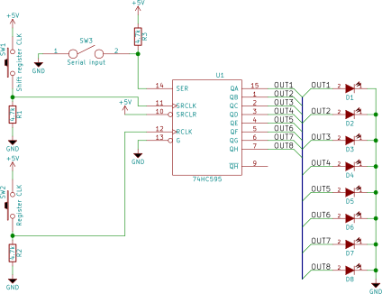
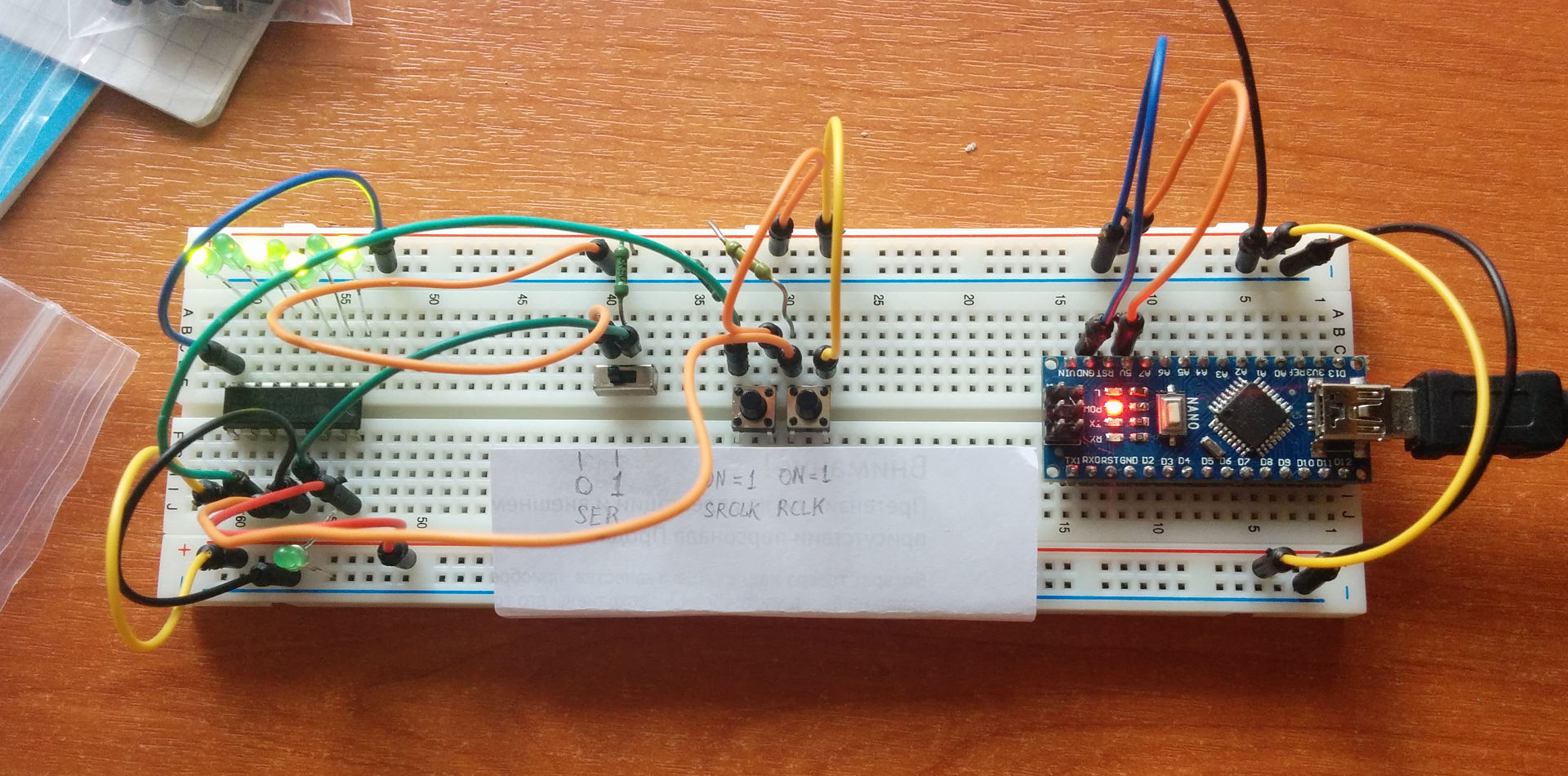
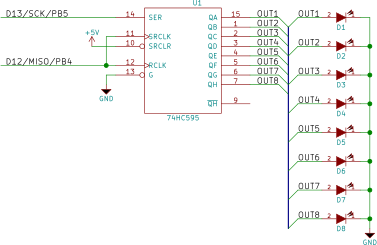
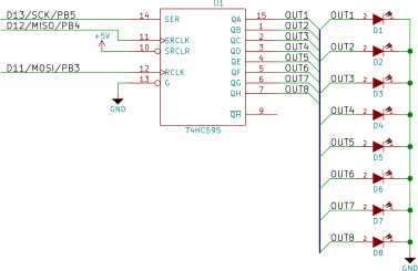
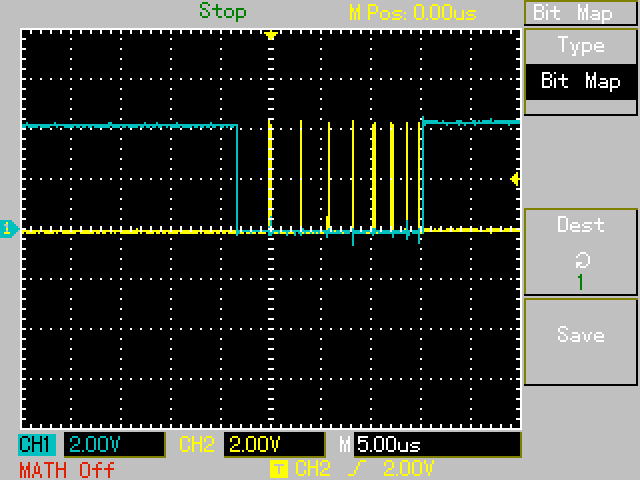
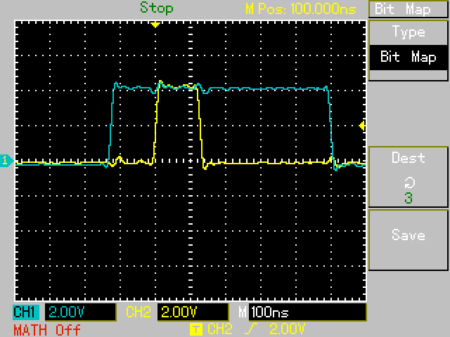
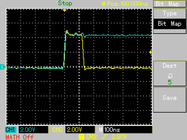
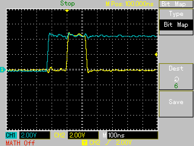
    <content type="html"><![CDATA[<p>Arduino Nano is a pretty cheap single-board microcontroller kit. It’s very useful for a tasks like generating specific signal, programming EEPROM, etc. For example Ben Eater <a href="https://eater.net/bbcpu8-output-register/" target="_blank" rel="noopener">uses it to program EEPROM</a>. If you want to build a great device from scratch I still recommend you <a href="http://localhost:4000/en/stm32-l152-libopencm/" target="_blank" rel="noopener">STM32</a> but if you want to solve some problem very quickly (and perhaps dirty), you can use AVR microcontroller inside the Arduino Nano. In this article I’ll show you how to program Arduino Nano on Ubuntu to drive 74HC595 shift register.</p><a id="more"></a><h2 id="The-problem"><a href="#The-problem" class="headerlink" title="The problem"></a>The problem</h2><p>Using shift registers is a common practice in the cases when you need a lot of low-frequency digital signals or connecting serial communication line (like USB) to a bus with a parallel interface. In this tutorial I’ll obtain 8-bit signal out of Arduino Nano using only 3 output pins. To do that I’ll use 74HC595 shift register and a breadboard.</p><p>First of all lets connect shift register to the push-buttons to take an intuition of working with it:</p><img src="/en/shift-register-arduino-nano/shift-register-manual.svg" title="Manually driven shift register scheme"><p>Here’s my breadboard:</p><img src="/en/shift-register-arduino-nano/shift-register-manual.jpg" title="Manually driven shift register breadboard"><p>A chip on the left is 74HC595 shift register. You see a switch and push buttons in the middle. Arduino on the right is only for obtaining the power (GND and +5V). You’re able to look at Ben Eater manually controlling his shift register <a href="https://youtu.be/K88pgWhEb1M?t=5m5s" target="_blank" rel="noopener">here</a>.</p><h2 id="Using-Arduino-Nano-to-control-shift-register"><a href="#Using-Arduino-Nano-to-control-shift-register" class="headerlink" title="Using Arduino Nano to control shift register"></a>Using Arduino Nano to control shift register</h2><p>Lets connect our microcontroller kit to the shift register. <a href="/en/shift-register-arduino-nano/arduino-nano-rev-3.2.pdf" title="Arduino Nano's scheme">Arduino Nano's scheme</a> (PDF, 79 KiB) may be very helpful. We’re using just two Arduino’s pins now: <code>D12</code> and <code>D13</code>. <code>D13</code> is also connected to the Arduino’s LED so we’re able to look at serial data transmission.</p><img src="/en/shift-register-arduino-nano/shift-register-demo.svg" title="Arduino Nano driven shift register scheme"><p>Install some packages to program AVR microcontrollers (if you’re using APT):</p><figure class="highlight sh"><table><tr><td class="code"><pre><span class="line">sudo apt install avr-libc avrdude binutils-avr gcc-avr srecord</span><br></pre></td></tr></table></figure><p>You’re able to take the source code from <a href="https://github.com/quasiyoke/shift-register-arduino-nano" target="_blank" rel="noopener">my GitHub repo</a>:</p><figure class="highlight sh"><table><tr><td class="code"><pre><span class="line">git <span class="built_in">clone</span> https://github.com/quasiyoke/<span class="built_in">shift</span>-register-arduino-nano.git</span><br><span class="line">git checkout <span class="built_in">shift</span>-register-demo</span><br></pre></td></tr></table></figure><p>To compile your source code you’ll need to run several console commands. I’ve found a great <code>Makefile</code> helping in that <a href="https://electronics.stackexchange.com/a/66163/93978" target="_blank" rel="noopener">here</a>. I’ve customized it in several ways:</p><ol><li>changed the programming language from C++ to C (there’re some <a href="https://www.microchip.com/webdoc/AVRLibcReferenceManual/FAQ_1faq_cplusplus.html" target="_blank" rel="noopener">considerations</a> for doing that),</li><li>removed fuses flashing (their default configuration is OK usually),</li><li>changed BAUD rate, clock frequency and MCU type according to our hardware (ATMega328P).</li></ol><p>Please note that <code>Makefile</code> should be indented using tabs instead of spaces – this is very important requirement. Here’s the <code>Makefile</code> contents:</p><figure class="highlight makefile"><table><tr><td class="code"><pre><span class="line">baud=57600</span><br><span class="line">src=src/main</span><br><span class="line">build=build</span><br><span class="line">asset=project</span><br><span class="line">avrType=atmega328</span><br><span class="line">avrFreq=16000000</span><br><span class="line">programmerDev=/dev/ttyUSB0</span><br><span class="line">programmerType=arduino</span><br><span class="line"></span><br><span class="line">cflags=-std=c99 -g -DF_CPU=<span class="variable">$(avrFreq)</span> -Wall -Os -Werror -Wextra</span><br><span class="line"></span><br><span class="line">memoryTypes=calibration eeprom efuse flash fuse hfuse lfuse lock signature application apptable boot prodsig usersig</span><br><span class="line"></span><br><span class="line"><span class="meta"><span class="meta-keyword">.PHONY</span>: backup clean disassemble dumpelf eeprom elf flash help hex makefile object program</span></span><br><span class="line"></span><br><span class="line"><span class="section">help:</span></span><br><span class="line">  @echo 'backup       Read all known memory types from controller and write it into a file. Available memory types: <span class="variable">$(memoryTypes)</span>'</span><br><span class="line">  @echo 'clean        Delete automatically created files.'</span><br><span class="line">  @echo 'disassemble  Compile source code, then disassemble object file to mnemonics.'</span><br><span class="line">  @echo 'dumpelf      Dump the contents of the .elf file. Useful for information purposes only.'</span><br><span class="line">  @echo 'eeprom       Extract EEPROM data from .elf file and program the device with it.'</span><br><span class="line">  @echo 'elf          Create <span class="variable">$(build)</span>/<span class="variable">$(asset)</span>.elf'</span><br><span class="line">  @echo 'flash        Program <span class="variable">$(build)</span>/<span class="variable">$(asset)</span>.hex to controller flash memory.'</span><br><span class="line">  @echo 'help         Show this text.'</span><br><span class="line">  @echo 'hex          Create all hex files for flash, eeprom.'</span><br><span class="line">  @echo 'object       Create <span class="variable">$(build)</span>/<span class="variable">$(asset)</span>.o'</span><br><span class="line">  @echo 'program      Do all programming to controller.'</span><br><span class="line"></span><br><span class="line"><span class="comment">#all: object elf hex</span></span><br><span class="line"></span><br><span class="line"><span class="section">clean:</span></span><br><span class="line">  rm -f <span class="variable">$(build)</span>/<span class="variable">$(asset)</span>.elf <span class="variable">$(build)</span>/<span class="variable">$(asset)</span>.eeprom.hex <span class="variable">$(build)</span>/<span class="variable">$(asset)</span>.flash.hex <span class="variable">$(build)</span>/<span class="variable">$(asset)</span>.o <span class="variable">$(build)</span>/<span class="variable">$(asset)</span>.lst</span><br><span class="line">  rm -df <span class="variable">$(build)</span></span><br><span class="line">  @date</span><br><span class="line"></span><br><span class="line"><span class="variable">$(build)</span>:</span><br><span class="line">  mkdir <span class="variable">$(build)</span></span><br><span class="line"></span><br><span class="line"><span class="section">object: <span class="variable">$(build)</span></span></span><br><span class="line">  avr-gcc <span class="variable">$(cflags)</span> -mmcu=<span class="variable">$(avrType)</span> -Wa,-ahlmns=<span class="variable">$(build)</span>/<span class="variable">$(asset)</span>.lst -c -o <span class="variable">$(build)</span>/<span class="variable">$(asset)</span>.o <span class="variable">$(src)</span>.c</span><br><span class="line"></span><br><span class="line"><span class="section">elf: object</span></span><br><span class="line">  avr-gcc <span class="variable">$(cflags)</span> -mmcu=<span class="variable">$(avrType)</span> -o <span class="variable">$(build)</span>/<span class="variable">$(asset)</span>.elf <span class="variable">$(build)</span>/<span class="variable">$(asset)</span>.o</span><br><span class="line">  chmod a-x <span class="variable">$(build)</span>/<span class="variable">$(asset)</span>.elf 2&gt;&amp;1</span><br><span class="line"></span><br><span class="line"><span class="section">hex: elf</span></span><br><span class="line">  avr-objcopy -j .text -j .data -O ihex <span class="variable">$(build)</span>/<span class="variable">$(asset)</span>.elf <span class="variable">$(build)</span>/<span class="variable">$(asset)</span>.flash.hex</span><br><span class="line">  avr-objcopy -j .eeprom --set-section-flags=.eeprom=<span class="string">"alloc,load"</span> --change-section-lma .eeprom=0 -O ihex <span class="variable">$(build)</span>/<span class="variable">$(asset)</span>.elf <span class="variable">$(build)</span>/<span class="variable">$(asset)</span>.eeprom.hex</span><br><span class="line"></span><br><span class="line"><span class="section">disassemble: elf</span></span><br><span class="line">  avr-objdump -s -j .fuse <span class="variable">$(build)</span>/<span class="variable">$(asset)</span>.elf</span><br><span class="line">  avr-objdump -C -d <span class="variable">$(build)</span>/<span class="variable">$(asset)</span>.elf 2&gt;&amp;1</span><br><span class="line"></span><br><span class="line"><span class="section">eeprom: hex</span></span><br><span class="line">  <span class="comment">#avrdude -p$(avrType) -c$(programmerType) -P$(programmerDev) -b$(baud) -v -U eeprom:w:$(build)/$(asset).eeprom.hex</span></span><br><span class="line">  @date</span><br><span class="line"></span><br><span class="line"><span class="section">dumpelf: elf</span></span><br><span class="line">  avr-objdump -s -h <span class="variable">$(build)</span>/<span class="variable">$(asset)</span>.elf</span><br><span class="line"></span><br><span class="line"><span class="section">program: flash eeprom</span></span><br><span class="line"></span><br><span class="line"><span class="section">flash: hex</span></span><br><span class="line">  avrdude -p<span class="variable">$(avrType)</span> -c<span class="variable">$(programmerType)</span> -P<span class="variable">$(programmerDev)</span> -b<span class="variable">$(baud)</span> -v -U flash:w:<span class="variable">$(build)</span>/<span class="variable">$(asset)</span>.flash.hex</span><br><span class="line">  @date</span><br><span class="line"></span><br><span class="line"><span class="section">backup:</span></span><br><span class="line">  @for memory in <span class="variable">$(memoryTypes)</span>; do \</span><br><span class="line">    avrdude -p <span class="variable">$(avrType)</span> -c<span class="variable">$(programmerType)</span> -P<span class="variable">$(programmerDev)</span> -b<span class="variable">$(baud)</span> -v -U $$memory:r:./<span class="variable">$(avrType)</span>.$$memory.hex:i; \</span><br><span class="line">  done</span><br></pre></td></tr></table></figure><p>Here’s the source code from <code>src/main.c</code>:</p><figure class="highlight c"><table><tr><td class="code"><pre><span class="line"><span class="meta">#<span class="meta-keyword">include</span> <span class="meta-string">&lt;avr/io.h&gt;</span></span></span><br><span class="line"><span class="meta">#<span class="meta-keyword">include</span> <span class="meta-string">&lt;util/delay.h&gt;</span></span></span><br><span class="line"></span><br><span class="line"><span class="meta">#<span class="meta-keyword">define</span> BYTE_LENGTH (8)</span></span><br><span class="line"><span class="meta">#<span class="meta-keyword">define</span> LED_PIN (PB5)</span></span><br><span class="line"><span class="meta">#<span class="meta-keyword">define</span> SERIAL_OUTPUT_PIN (LED_PIN)</span></span><br><span class="line"><span class="meta">#<span class="meta-keyword">define</span> CLK_PIN (PB4)</span></span><br><span class="line"></span><br><span class="line"><span class="keyword">const</span> <span class="keyword">char</span> MESSAGE[] = &#123;</span><br><span class="line">  <span class="number">0b00000000</span>,</span><br><span class="line">  <span class="number">0b10101010</span>,</span><br><span class="line">  <span class="number">0b11111111</span>,</span><br><span class="line">  <span class="number">0b00110011</span>,</span><br><span class="line">&#125;;</span><br><span class="line"></span><br><span class="line"><span class="function"><span class="keyword">int</span> <span class="title">main</span><span class="params">(<span class="keyword">void</span>)</span> </span>&#123;</span><br><span class="line">  DDRB = _BV(SERIAL_OUTPUT_PIN)</span><br><span class="line">    | _BV(CLK_PIN);</span><br><span class="line"></span><br><span class="line">  <span class="keyword">for</span> (<span class="keyword">int</span> i = <span class="number">0</span>; ; i = (i + <span class="number">1</span>) % <span class="keyword">sizeof</span>(MESSAGE)) &#123;</span><br><span class="line">    <span class="keyword">char</span> valueByte = MESSAGE[i];</span><br><span class="line"></span><br><span class="line">    <span class="keyword">for</span> (<span class="keyword">char</span> j = BYTE_LENGTH - <span class="number">1</span>; j &gt;= <span class="number">0</span>; --j) &#123;</span><br><span class="line">      <span class="keyword">char</span> valueBit = (valueByte &gt;&gt; j) &amp; <span class="number">1</span>;</span><br><span class="line">      <span class="comment">// Set serial output to `0`</span></span><br><span class="line">      PORTB &amp;= ~(_BV(SERIAL_OUTPUT_PIN));</span><br><span class="line">      <span class="comment">// Send current bit value to serial output</span></span><br><span class="line">      PORTB |= valueBit &lt;&lt; SERIAL_OUTPUT_PIN;</span><br><span class="line">      <span class="comment">// Make a rising edge of clock signal</span></span><br><span class="line">      PORTB |= _BV(CLK_PIN);</span><br><span class="line">      <span class="comment">// Make a falling edge of clock signal</span></span><br><span class="line">      PORTB &amp;= ~(_BV(CLK_PIN));</span><br><span class="line">      _delay_ms(<span class="number">250</span>);</span><br><span class="line">    &#125;</span><br><span class="line">  &#125;</span><br><span class="line">&#125;</span><br></pre></td></tr></table></figure><p>To compile and flash the program, execute:</p><figure class="highlight sh"><table><tr><td class="code"><pre><span class="line">sudo make flash</span><br></pre></td></tr></table></figure><p>Here’s a video of this program working:</p><video autoplay loop><br>  <source src="/en/shift-register-arduino-nano/shift-register-demo.mp4" type="video/mp4"><br></video><h2 id="Bit-manipulation"><a href="#Bit-manipulation" class="headerlink" title="Bit manipulation"></a>Bit manipulation</h2><p>Note that the line:</p><figure class="highlight c"><table><tr><td class="code"><pre><span class="line">PORTB |= _BV(SHIFT_REGISTER_CLK_PIN);</span><br></pre></td></tr></table></figure><p>compiles to single assembly language instruction:</p><figure class="highlight plain"><table><tr><td class="code"><pre><span class="line">sbi 0x05, 4</span><br></pre></td></tr></table></figure><p>This instruction does exactly what we want: sets fourth bit (<code>PB4</code>) of the fith I/O port (<code>PORTB</code>) to <code>1</code>. You’re able to look at <a href="/en/shift-register-arduino-nano/atmega328p.pdf" title="ATMega328P datasheet">ATMega328P datasheet</a> (PDF, 5.1 MiB, page 433) to check that.</p><p>This line:</p><figure class="highlight c"><table><tr><td class="code"><pre><span class="line">PORTB &amp;= ~(_BV(SHIFT_REGISTER_CLK_PIN));</span><br></pre></td></tr></table></figure><p>compiles to single assembly instruction too:</p><figure class="highlight plain"><table><tr><td class="code"><pre><span class="line">cbi 0x05, 4</span><br></pre></td></tr></table></figure><p>and sets <code>PB4</code> to <code>0</code>. That’s all thanks to <a href="https://www.microchip.com/webdoc/AVRLibcReferenceManual/group__avr__sfr.html" target="_blank" rel="noopener">AVR Libc input/output optimizations</a>.</p><p><code>_BV</code> macro refers to “bit value” and <a href="https://www.microchip.com/webdoc/AVRLibcReferenceManual/group__avr__sfr_1ga11643f271076024c395a93800b3d9546.html" target="_blank" rel="noopener">was defined</a> in AVR Libc as follows:</p><figure class="highlight c"><table><tr><td class="code"><pre><span class="line"><span class="meta">#<span class="meta-keyword">define</span> _BV(bit) \</span></span><br><span class="line">  (<span class="number">1</span> &lt;&lt; (bit))</span><br></pre></td></tr></table></figure><h2 id="Controlling-74HC595’s-storage-register"><a href="#Controlling-74HC595’s-storage-register" class="headerlink" title="Controlling 74HC595’s storage register"></a>Controlling 74HC595’s storage register</h2><p>Usually there’s no need to see how does shift register fills in: we need ready-to-use bytes out of it. For that purpose 74HC595 has internal storage register. To control it we need to use third Arduino’s pin <code>DD11</code>:</p><img src="/en/shift-register-arduino-nano/shift-register-with-storage-register.svg" title="Arduino Nano driven shift register with a storage register scheme"><p>Lets change our program to control storage register. Checkout <code>shift-register-with-storage-register</code> GIT tag or change the source code manually:</p><figure class="highlight c"><table><tr><td class="code"><pre><span class="line"><span class="meta">#<span class="meta-keyword">include</span> <span class="meta-string">&lt;avr/io.h&gt;</span></span></span><br><span class="line"><span class="meta">#<span class="meta-keyword">include</span> <span class="meta-string">&lt;util/delay.h&gt;</span></span></span><br><span class="line"></span><br><span class="line"><span class="meta">#<span class="meta-keyword">define</span> BYTE_LENGTH (8)</span></span><br><span class="line"><span class="meta">#<span class="meta-keyword">define</span> LED_PIN (PB5)</span></span><br><span class="line"><span class="meta">#<span class="meta-keyword">define</span> SERIAL_OUTPUT_PIN (LED_PIN)</span></span><br><span class="line"><span class="meta">#<span class="meta-keyword">define</span> SHIFT_REGISTER_CLK_PIN (PB4)</span></span><br><span class="line"><span class="meta">#<span class="meta-keyword">define</span> REGISTER_CLK_PIN (PB3)</span></span><br><span class="line"></span><br><span class="line"><span class="keyword">const</span> <span class="keyword">char</span> MESSAGE[] = &#123;</span><br><span class="line">  <span class="number">0b00000000</span>,</span><br><span class="line">  <span class="number">0b10101010</span>,</span><br><span class="line">  <span class="number">0b11111111</span>,</span><br><span class="line">  <span class="number">0b00110011</span>,</span><br><span class="line">&#125;;</span><br><span class="line"></span><br><span class="line"><span class="function"><span class="keyword">int</span> <span class="title">main</span><span class="params">(<span class="keyword">void</span>)</span> </span>&#123;</span><br><span class="line">  DDRB = _BV(SERIAL_OUTPUT_PIN)</span><br><span class="line">    | _BV(SHIFT_REGISTER_CLK_PIN)</span><br><span class="line">    | _BV(REGISTER_CLK_PIN);</span><br><span class="line"></span><br><span class="line">  <span class="keyword">for</span> (<span class="keyword">int</span> i = <span class="number">0</span>; ; i = (i + <span class="number">1</span>) % <span class="keyword">sizeof</span>(MESSAGE)) &#123;</span><br><span class="line">    <span class="keyword">char</span> valueByte = MESSAGE[i];</span><br><span class="line">    <span class="comment">// Make a falling edge of storage register clock signal</span></span><br><span class="line">    PORTB &amp;= ~(_BV(REGISTER_CLK_PIN));</span><br><span class="line"></span><br><span class="line">    <span class="keyword">for</span> (<span class="keyword">char</span> j = BYTE_LENGTH - <span class="number">1</span>; j &gt;= <span class="number">0</span>; --j) &#123;</span><br><span class="line">      <span class="keyword">char</span> valueBit = (valueByte &gt;&gt; j) &amp; <span class="number">1</span>;</span><br><span class="line">      <span class="comment">// Set serial output to `0`</span></span><br><span class="line">      PORTB &amp;= ~(_BV(SERIAL_OUTPUT_PIN));</span><br><span class="line">      <span class="comment">// Send current bit value to serial output</span></span><br><span class="line">      PORTB |= valueBit &lt;&lt; SERIAL_OUTPUT_PIN;</span><br><span class="line">      <span class="comment">// Make a rising edge of shift register clock signal</span></span><br><span class="line">      PORTB |= _BV(SHIFT_REGISTER_CLK_PIN);</span><br><span class="line">      <span class="comment">// Make a falling edge of shift register clock signal</span></span><br><span class="line">      PORTB &amp;= ~(_BV(SHIFT_REGISTER_CLK_PIN));</span><br><span class="line">    &#125;</span><br><span class="line"></span><br><span class="line">    <span class="comment">// Make a rising edge of storage register clock signal</span></span><br><span class="line">    PORTB |= _BV(REGISTER_CLK_PIN);</span><br><span class="line">    _delay_ms(<span class="number">250</span>);</span><br><span class="line">  &#125;</span><br><span class="line">&#125;</span><br></pre></td></tr></table></figure><p>This program works very well. It shows information on the LEDs byte-by-byte hiding shift register operation inside the chip. It looks more boring than a previous setup but it’s more useful in practice:</p><video autoplay loop><br>  <source src="/en/shift-register-arduino-nano/shift-register-with-storage-register.mp4" type="video/mp4"><br></video><p>I’ve captured signals coming out of Arduino Nano using my oscilloscope:</p><img src="/en/shift-register-arduino-nano/rclk-and-srclk.png" title="Storage register clock and shift register clock signals oscillogram"><p>On a channel 1 (blue) you see the storage register clock signal. On a channel 2 (yellow) you see shift register clock signal. Microcontroller pushes a byte of data into the shift register bit-by-bit with a shift register clock and outputs the whole byte on a positive edge of the storage register clock signal.</p><p>Let’s see writing a single bit into the shift register in a more detail:</p><img src="/en/shift-register-arduino-nano/ser-and-srclk-01.png" title="Serial data and shift register clock signals oscillogram"><p>On a channel 1 (blue) you see the serial data signal now. On a channel 2 (yellow) you see shift register clock signal.</p><h2 id="Reducing-I-O-operations-count"><a href="#Reducing-I-O-operations-count" class="headerlink" title="Reducing I/O operations count"></a>Reducing I/O operations count</h2><p>Input/output operations (writing to the <code>PORTB</code>) are pretty slow and one should reduce their count if possible. For someone who’re used to do usual programming it looks like we’re able to optimize inner cycle this way (GIT tag <code>optimization</code>):</p><figure class="highlight c"><table><tr><td class="code"><pre><span class="line"><span class="keyword">for</span> (<span class="keyword">char</span> j = BYTE_LENGTH - <span class="number">1</span>; j &gt;= <span class="number">0</span>; --j) &#123;</span><br><span class="line">  <span class="keyword">char</span> valueBit = (valueByte &gt;&gt; j) &amp; <span class="number">1</span>;</span><br><span class="line">  <span class="comment">/*</span></span><br><span class="line"><span class="comment">   * Send current bit value to serial output and</span></span><br><span class="line"><span class="comment">   * make rising edge of shift register clock signal</span></span><br><span class="line"><span class="comment">   * with only one I/O operation</span></span><br><span class="line"><span class="comment">   */</span></span><br><span class="line">  PORTB = valueBit &lt;&lt; SERIAL_OUTPUT_PIN</span><br><span class="line">    | _BV(SHIFT_REGISTER_CLK_PIN);</span><br><span class="line">  <span class="comment">// Make a falling edge of shift register clock</span></span><br><span class="line">  PORTB &amp;= ~(_BV(SHIFT_REGISTER_CLK_PIN));</span><br><span class="line">&#125;</span><br></pre></td></tr></table></figure><p>Unfortunatelly, this won’t work. Such a program makes shift register to decode serial signal incorrectly: delayed by one bit! You won’t find any troubles inside the program if you disassemble it. The key of solving the problem lays in an oscillogram:</p><img src="/en/shift-register-arduino-nano/ser-and-srclk-simultaneously.png" title="Serial data and shift register clock signals oscillogram"><p>Natural result of joining several I/O operations into one is that serial data signal and shift register clock rising edges are simultaneous now. But <a href="/en/shift-register-arduino-nano/74hc595.pdf" title="SNx4HC595 datasheet">SNx4HC595 datasheet</a> (PDF, 2.1 MiB) says (on a page 7) that set-up time between serial data signal edge (<code>SER</code>) and shift register clock edge (<code>SRCLK</code>) should be at least 20 ns (30 ns in a worst case). This fact is a good reason to make one more I/O operation (checkout GIT branch <code>master</code>):</p><figure class="highlight c"><table><tr><td class="code"><pre><span class="line"><span class="keyword">for</span> (<span class="keyword">char</span> j = BYTE_LENGTH - <span class="number">1</span>; j &gt;= <span class="number">0</span>; --j) &#123;</span><br><span class="line">  <span class="keyword">char</span> valueBit = (valueByte &gt;&gt; j) &amp; <span class="number">1</span>;</span><br><span class="line">  <span class="comment">// Send current bit value to serial output</span></span><br><span class="line">  PORTB = valueBit &lt;&lt; SERIAL_OUTPUT_PIN;</span><br><span class="line">  <span class="comment">// Make rising edge of shift register clock signal</span></span><br><span class="line">  PORTB |= _BV(SHIFT_REGISTER_CLK_PIN);</span><br><span class="line">  <span class="comment">// Make a falling edge of shift register clock</span></span><br><span class="line">  PORTB &amp;= ~(_BV(SHIFT_REGISTER_CLK_PIN));</span><br><span class="line">&#125;</span><br></pre></td></tr></table></figure><p>This time our program works correctly:</p><img src="/en/shift-register-arduino-nano/ser-and-srclk-02.png" title="Serial data and shift register clock signals oscillogram"><p>Notice that last listing differs from the first variant of the program by omitting the stage of “Setting serial output to <code>0</code>“. This way we’ve reduced amount of I/O operations from 4 to 3 with keeping our setup functional.</p><h2 id="Disassembling-your-object-files"><a href="#Disassembling-your-object-files" class="headerlink" title="Disassembling your object files"></a>Disassembling your object files</h2><p>There’s a couple of situations when you need to look at the compiled program’s instructions to have a complete understanding of its work. You’re able to do that with AVR GCC toolkit.</p><p>First of all change permissions of <code>build</code> directory (because it was set to <code>root</code> during the flashing):</p><figure class="highlight sh"><table><tr><td class="code"><pre><span class="line">sudo chown -R <span class="variable">$USER</span> build</span><br></pre></td></tr></table></figure><p>Now you’re able to disassemble your object file:</p><figure class="highlight sh"><table><tr><td class="code"><pre><span class="line">avr-objdump --<span class="built_in">source</span> build/project.elf &gt; build/listing.lst</span><br></pre></td></tr></table></figure><p>The <code>--source</code> option intersperses initial C code in the output.</p><p>Here’s the listing’s fragment of the last version of the program:</p><figure class="highlight plain"><table><tr><td class="code"><pre><span class="line">a8: 47 e0         ldi r20, 0x07 ; 7</span><br><span class="line">aa: 50 e0         ldi r21, 0x00 ; 0</span><br><span class="line"></span><br><span class="line">  for (char j = BYTE_LENGTH - 1; j &gt;= 0; --j) &#123;</span><br><span class="line">    char valueBit = (valueByte &gt;&gt; j) &amp; 1;</span><br><span class="line">ac: 06 2e         mov r0, r22</span><br><span class="line">ae: 00 0c         add r0, r0</span><br><span class="line">b0: 77 0b         sbc r23, r23</span><br><span class="line">b2: 9b 01         movw  r18, r22</span><br><span class="line">b4: 04 2e         mov r0, r20</span><br><span class="line">b6: 02 c0         rjmp  .+4       ; 0xbc &lt;main+0x26&gt;</span><br><span class="line">b8: 35 95         asr r19</span><br><span class="line">ba: 27 95         ror r18</span><br><span class="line">bc: 0a 94         dec r0</span><br><span class="line">be: e2 f7         brpl  .-8       ; 0xb8 &lt;main+0x22&gt;</span><br><span class="line">c0: 21 70         andi  r18, 0x01 ; 1</span><br><span class="line">    PORTB = valueBit &lt;&lt; SERIAL_OUTPUT_PIN;</span><br><span class="line">c2: 22 95         swap  r18</span><br><span class="line">c4: 22 0f         add r18, r18</span><br><span class="line">c6: 20 7e         andi  r18, 0xE0 ; 224</span><br><span class="line">c8: 25 b9         out 0x05, r18 ; 5</span><br><span class="line">    PORTB |= _BV(SHIFT_REGISTER_CLK_PIN);</span><br><span class="line">ca: 2c 9a         sbi 0x05, 4 ; 5</span><br><span class="line">    PORTB &amp;= ~(_BV(SHIFT_REGISTER_CLK_PIN));</span><br><span class="line">cc: 2c 98         cbi 0x05, 4 ; 5</span><br><span class="line">ce: 41 50         subi  r20, 0x01 ; 1</span><br><span class="line">d0: 51 09         sbc r21, r1</span><br><span class="line">d2: 78 f7         brcc  .-34      ; 0xb2 &lt;main+0x1c&gt;</span><br><span class="line">  &#125;</span><br><span class="line"></span><br><span class="line">  PORTB |= _BV(REGISTER_CLK_PIN);</span><br><span class="line">d4: 2b 9a         sbi 0x05, 3 ; 5</span><br></pre></td></tr></table></figure><p>You see a weird way of doing bit shift (offsets <code>b4</code>–<code>be</code>) and as compiler optimizes I/O operations (offsets <code>ca</code>, <code>cc</code>, <code>d4</code>). Such listing is obviously may be very useful.</p><h2 id="Conclusion"><a href="#Conclusion" class="headerlink" title="Conclusion"></a>Conclusion</h2><p>Perhaps, you’ve noticed at the oscillogram that microcontroller pushes each subsequent bit of a single byte faster and faster. The program sends most significant bits slower than less significant because of bit shifting operation. To make microcontroller shift bits for a constant time will be a good hometask for you.</p><p>I hope this post will help you to start working with AVR microcontrollers on Ubuntu.</p>]]></content>
    
    <summary type="html">
    
      &lt;p&gt;Arduino Nano is a pretty cheap single-board microcontroller kit. It’s very useful for a tasks like generating specific signal, programming EEPROM, etc. For example Ben Eater &lt;a href=&quot;https://eater.net/bbcpu8-output-register/&quot; target=&quot;_blank&quot; rel=&quot;noopener&quot;&gt;uses it to program EEPROM&lt;/a&gt;. If you want to build a great device from scratch I still recommend you &lt;a href=&quot;http://localhost:4000/en/stm32-l152-libopencm/&quot; target=&quot;_blank&quot; rel=&quot;noopener&quot;&gt;STM32&lt;/a&gt; but if you want to solve some problem very quickly (and perhaps dirty), you can use AVR microcontroller inside the Arduino Nano. In this article I’ll show you how to program Arduino Nano on Ubuntu to drive 74HC595 shift register.&lt;/p&gt;
    
    </summary>
    
    
      <category term="mcu" scheme="https://quasiyoke.me/tags/mcu/"/>
    
      <category term="ubuntu" scheme="https://quasiyoke.me/tags/ubuntu/"/>
    
      <category term="avr" scheme="https://quasiyoke.me/tags/avr/"/>
    
      <category term="74hc595" scheme="https://quasiyoke.me/tags/74hc595/"/>
    
      <category term="shift register" scheme="https://quasiyoke.me/tags/shift-register/"/>
    
      <category term="arduino" scheme="https://quasiyoke.me/tags/arduino/"/>
    
  </entry>
  
  <entry>
    <title>STM32 L152 programming with libopencm3</title>
    <link href="https://quasiyoke.me/en/stm32-l152-libopencm/"/>
    <id>https://quasiyoke.me/en/stm32-l152-libopencm/</id>
    <published>2016-09-18T14:06:00.000Z</published>
    <updated>2021-01-02T01:07:18.066Z</updated>
    
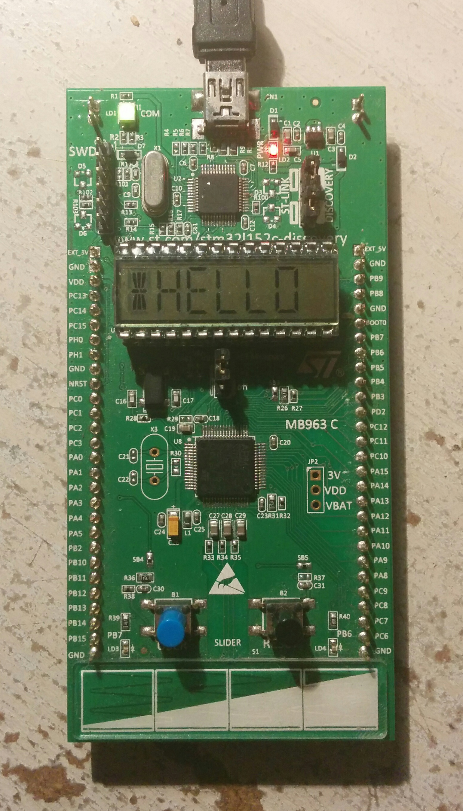
    <content type="html"><![CDATA[<p>In my <a href="/en/stm32-l152-discovery-toolchain/">last post</a> I’ve described long way of configuring non-proprietary toolchain for ARM programming. I was pretty satisfied with it except two of its elements: Eclipse (I’m not a fan of large IDEs) and proprietary STM32 L1 standard peripheral library. The post have also covered cherry-picking of needed files from this libray to transform STM32 <strong>F1</strong> blinking “hello world” to STM32 <strong>L1</strong> blinking project. Today I’ve found much faster way to start STM32 L1 programming.</p><a id="more"></a><p>This article’s toolchain consist of:</p><ol><li>Any text editor (I prefer Sublime Text),</li><li>GNU ARM Embedded toolchain,</li><li>OpenOCD,</li><li>Open source STLINK tool.</li></ol><p>As you can see, I’ve used most of the parts from my last post. This toolchain will give you even more control and transparency on building process and of course it doesn’t have any proprietary software in it (except Sublime, but you’re able to use Atom or Vim).</p><p>You need some library to program your microcontroller (MCU) because usually you need to operate a plenty of sophisticated registers. All these registers usually have addresses like this: <code>0x40020C00</code>. It’s better to operate with some human-readable code instead of all this digits, so you either need to define addresses as constants by yourself or use a library written by experienced developers. In my last post I used proprietary STM32 L1 standard peripheral library. Today I’m going to show you how to use <a href="http://libopencm3.org/" target="_blank" rel="noopener">GNU libopencm3</a> for that.</p><h2 id="GNU-ARM-Embedded-toolchain"><a href="#GNU-ARM-Embedded-toolchain" class="headerlink" title="GNU ARM Embedded toolchain"></a>GNU ARM Embedded toolchain</h2><p>I’m going to repeat installation steps from last article here to achieve completeness of this guide. So, usual APT commands for installing ARM cross-compilation tools (assuming you’re using some Debian-based distribution like Ubuntu):</p><figure class="highlight sh"><table><tr><td class="code"><pre><span class="line">sudo add-apt-repository ppa:team-gcc-arm-embedded/ppa</span><br><span class="line">sudo apt update</span><br><span class="line">sudo apt install gcc-arm-none-eabi gdb-arm-none-eabi</span><br></pre></td></tr></table></figure><p>If installation finished correctly you should be able to test toolchain’s version.</p><figure class="highlight sh"><table><tr><td class="code"><pre><span class="line">arm-none-eabi-gcc --version</span><br></pre></td></tr></table></figure><h2 id="OpenOCD"><a href="#OpenOCD" class="headerlink" title="OpenOCD"></a>OpenOCD</h2><p>Setting up the tool for hardware debugging.</p><figure class="highlight sh"><table><tr><td class="code"><pre><span class="line">sudo apt install openocd</span><br></pre></td></tr></table></figure><h2 id="Open-source-STLINK-tool"><a href="#Open-source-STLINK-tool" class="headerlink" title="Open source STLINK tool"></a>Open source STLINK tool</h2><figure class="highlight sh"><table><tr><td class="code"><pre><span class="line"><span class="built_in">cd</span> ~/Downloads/</span><br><span class="line">git <span class="built_in">clone</span> https://github.com/texane/stlink.git</span><br><span class="line"><span class="built_in">cd</span> ~/Downloads/stlink/</span><br><span class="line">sudo install -m 644 etc/udev/rules.d/49-stlinkv2.rules /etc/udev/rules.d/49-stlinkv2.rules</span><br><span class="line">sudo udevadm control --reload-rules</span><br></pre></td></tr></table></figure><h2 id="libopencm3-examples"><a href="#libopencm3-examples" class="headerlink" title="libopencm3 examples"></a>libopencm3 examples</h2><p><a href="http://libopencm3.org/" target="_blank" rel="noopener">libopencm3</a> is a GNU alternative for STM32 standard peripheral libraries. The project’s GitHub contains <a href="https://github.com/libopencm3/libopencm3-examples" target="_blank" rel="noopener">libopencm3 examples repository</a>. If you clone this repo you’ll be able to build any example and flash it with simple terminal commands.</p><figure class="highlight sh"><table><tr><td class="code"><pre><span class="line">git <span class="built_in">clone</span> https://github.com/libopencm3/libopencm3-examples.git</span><br><span class="line"><span class="built_in">cd</span> libopencm3-examples</span><br><span class="line">git submodule init</span><br><span class="line">git submodule update</span><br><span class="line">make</span><br></pre></td></tr></table></figure><p>When I did it, building have stopped with error at building <code>examples/sam/d/d10-xplained-mini/miniblink/</code> stage (examples rev.: <code>9fbac7d</code>, libopencm3 rev.: <code>13d4302</code>). I don’t know what’s the reason of that but I don’t care about Atmel SAM. If you’ve got the same error ignore it, connect your STM32 L152 Discovery board through USB Mini-B cable and execute the following:</p><figure class="highlight sh"><table><tr><td class="code"><pre><span class="line"><span class="built_in">cd</span> examples/stm32/l1/stm32l-discovery/miniblink</span><br><span class="line">make flash</span><br></pre></td></tr></table></figure><p>And that’s it! After that your board should start blinking with its LED.</p><h2 id="LCD-ticker"><a href="#LCD-ticker" class="headerlink" title="LCD ticker"></a>LCD ticker</h2><p>Let’s write some simple program using libopencm3 library. For example, LCD ticker.</p><img src="/en/stm32-l152-libopencm/news-ticker.jpg" title="News LED ticker"><p>The screen should display some text moving it forward rapidly.</p><h3 id="LCD-hello"><a href="#LCD-hello" class="headerlink" title="LCD hello"></a>LCD hello</h3><p>At first I recommend you to write some trivial example to make sure all your tools are working right.</p><section class="article__side-by-side"><div class="article__side-by-side-cell"><img src="/en/stm32-l152-libopencm/lcd-hello.jpg" title="STM32 L152 Discovery board showing &quot;*HELLO&quot; text"></div><div class="article__side-by-side-cell"><p>Let’s show some text at our screen. It’s already done at one of libopencm3 examples. This example just displays “*HELLO” string. I’ve copied it to <a href="https://github.com/quasiyoke/stm32-l152-lcd-ticker/tree/1-lcd-hello" target="_blank" rel="noopener">my repo</a> and adopted Makefile. The link is already pointing at the <code>1-lcd-hello</code> tag.</p><p>To flash the program on your board just execute this:</p><figure class="highlight sh"><table><tr><td class="code"><pre><span class="line">git <span class="built_in">clone</span> https://github.com/quasiyoke/stm32-l152-lcd-ticker.git</span><br><span class="line"><span class="built_in">cd</span> stm32-l152-lcd-ticker</span><br><span class="line">git checkout 1-lcd-hello -- .</span><br><span class="line">make flash</span><br></pre></td></tr></table></figure></div></section><p>Find <code>lcd_display_hello</code> function inside <code>main.c</code>. This function determines the text we’re showing. Try to specify some other string. For example: “BYEBYE”</p><figure class="highlight c"><table><tr><td class="code"><pre><span class="line"><span class="function"><span class="keyword">static</span> <span class="keyword">void</span> <span class="title">lcd_display_hello</span> <span class="params">(<span class="keyword">void</span>)</span></span></span><br><span class="line"><span class="function"></span>&#123;</span><br><span class="line">    <span class="keyword">do</span> &#123;&#125; <span class="keyword">while</span> (!lcd_is_for_update_ready ());</span><br><span class="line">    clear_lcd_ram (); <span class="comment">// all segments off</span></span><br><span class="line">    write_char_to_lcd_ram (<span class="number">0</span>, <span class="string">'B'</span>, <span class="literal">true</span>);</span><br><span class="line">    write_char_to_lcd_ram (<span class="number">1</span>, <span class="string">'Y'</span>, <span class="literal">true</span>);</span><br><span class="line">    write_char_to_lcd_ram (<span class="number">2</span>, <span class="string">'E'</span>, <span class="literal">true</span>);</span><br><span class="line">    write_char_to_lcd_ram (<span class="number">3</span>, <span class="string">'B'</span>, <span class="literal">true</span>);</span><br><span class="line">    write_char_to_lcd_ram (<span class="number">4</span>, <span class="string">'Y'</span>, <span class="literal">true</span>);</span><br><span class="line">    write_char_to_lcd_ram (<span class="number">5</span>, <span class="string">'E'</span>, <span class="literal">true</span>);</span><br><span class="line"></span><br><span class="line">    lcd_update ();</span><br><span class="line">&#125;</span><br></pre></td></tr></table></figure><p>After your modifications, flash MCU again:</p><figure class="highlight sh"><table><tr><td class="code"><pre><span class="line">make flash</span><br></pre></td></tr></table></figure><p>If you’ve broken something, don’t worry! Just checkout initial revision:</p><figure class="highlight sh"><table><tr><td class="code"><pre><span class="line">git checkout 1-lcd-hello -- .</span><br></pre></td></tr></table></figure><h3 id="Writing-LCD-ticker-code"><a href="#Writing-LCD-ticker-code" class="headerlink" title="Writing LCD ticker code"></a>Writing LCD ticker code</h3><p>We’ll make LCD ticker in two steps:</p><ol><li>Writing function which shows arbitrary text</li><li>Making the text move</li></ol><p>Let’s make <code>lcd_display_hello</code> show any string from some specified position. I think this function should have another name since that: <code>lcd_show</code>. Look at the code:</p><figure class="highlight c"><table><tr><td class="code"><pre><span class="line"><span class="comment">/**</span></span><br><span class="line"><span class="comment"> * Shows maximal possible part of the given text on LCD screen. If text is too</span></span><br><span class="line"><span class="comment"> * short, shows it cycled.</span></span><br><span class="line"><span class="comment"> * @param text Text to show</span></span><br><span class="line"><span class="comment"> * @param offset Positive offset inside the text from which we should</span></span><br><span class="line"><span class="comment"> *  start showing it</span></span><br><span class="line"><span class="comment"> */</span></span><br><span class="line"><span class="function"><span class="keyword">static</span> <span class="keyword">void</span> <span class="title">lcd_show</span><span class="params">(<span class="keyword">char</span>* text, <span class="keyword">int</span> offset)</span></span></span><br><span class="line"><span class="function"></span>&#123;</span><br><span class="line">    <span class="keyword">const</span> <span class="keyword">int</span> TEXT_LENGTH = <span class="built_in">strlen</span>(text);</span><br><span class="line"></span><br><span class="line">    <span class="keyword">do</span> &#123;&#125; <span class="keyword">while</span> (!lcd_is_for_update_ready());</span><br><span class="line"></span><br><span class="line">    <span class="keyword">for</span> (<span class="keyword">int</span> i=<span class="number">0</span>; i&lt;LCD_LETTERS_COUNT; ++i) &#123;</span><br><span class="line">        write_char_to_lcd_ram(i, text[(offset + i) % TEXT_LENGTH], <span class="literal">true</span>);</span><br><span class="line">    &#125;</span><br><span class="line"></span><br><span class="line">    lcd_update();</span><br><span class="line">&#125;</span><br></pre></td></tr></table></figure><p>This function is called from <code>main()</code> with <code>TEXT</code> specified at <code>main.h</code> file.</p><p>You’re able to try this code by executing this:</p><figure class="highlight sh"><table><tr><td class="code"><pre><span class="line">git checkout 2-lcd-show -- .</span><br><span class="line">make flash</span><br></pre></td></tr></table></figure><p>Try to change offset specified at <code>main</code> function to see different parts of the string on the screen or shorten the string to less than 6 characters to see it repeated.</p><h3 id="Moving-text"><a href="#Moving-text" class="headerlink" title="Moving text"></a>Moving text</h3><p>To make text move let’s add infinite cycle to <code>main()</code>:</p><figure class="highlight c"><table><tr><td class="code"><pre><span class="line"><span class="function"><span class="keyword">int</span> <span class="title">main</span><span class="params">(<span class="keyword">void</span>)</span></span></span><br><span class="line"><span class="function"></span>&#123;</span><br><span class="line">    <span class="keyword">const</span> <span class="keyword">int</span> TEXT_LENGTH = <span class="built_in">strlen</span>(TEXT);</span><br><span class="line"></span><br><span class="line">    lcd_init();</span><br><span class="line"></span><br><span class="line">    <span class="keyword">for</span> (<span class="keyword">int</span> offset=<span class="number">0</span>; ; ++offset, offset%=TEXT_LENGTH) &#123;</span><br><span class="line">        lcd_show(TEXT, offset);</span><br><span class="line"></span><br><span class="line">        <span class="comment">// Wait a bit</span></span><br><span class="line">        <span class="keyword">for</span> (<span class="keyword">int</span> i=<span class="number">0</span>; i&lt;<span class="number">100000</span>; ++i) &#123;</span><br><span class="line">            __asm__(<span class="string">"nop"</span>);</span><br><span class="line">        &#125;</span><br><span class="line">    &#125;</span><br><span class="line"></span><br><span class="line">    <span class="keyword">return</span> <span class="number">0</span>;</span><br><span class="line">&#125;</span><br></pre></td></tr></table></figure><p>And this is the final program as you can see it in <a href="https://github.com/quasiyoke/stm32-l152-lcd-ticker" target="_blank" rel="noopener">my repository</a>.</p><p><iframe width="560" height="315" src="https://www.youtube.com/embed/o7ARxiO41W8" frameborder="0" allowfullscreen></iframe></p><p>To flash it do the following:</p><figure class="highlight sh"><table><tr><td class="code"><pre><span class="line">git checkout master</span><br><span class="line">make flash</span><br></pre></td></tr></table></figure>]]></content>
    
    <summary type="html">
    
      &lt;p&gt;In my &lt;a href=&quot;/en/stm32-l152-discovery-toolchain/&quot;&gt;last post&lt;/a&gt; I’ve described long way of configuring non-proprietary toolchain for ARM programming. I was pretty satisfied with it except two of its elements: Eclipse (I’m not a fan of large IDEs) and proprietary STM32 L1 standard peripheral library. The post have also covered cherry-picking of needed files from this libray to transform STM32 &lt;strong&gt;F1&lt;/strong&gt; blinking “hello world” to STM32 &lt;strong&gt;L1&lt;/strong&gt; blinking project. Today I’ve found much faster way to start STM32 L1 programming.&lt;/p&gt;
    
    </summary>
    
    
      <category term="arm" scheme="https://quasiyoke.me/tags/arm/"/>
    
      <category term="mcu" scheme="https://quasiyoke.me/tags/mcu/"/>
    
      <category term="st" scheme="https://quasiyoke.me/tags/st/"/>
    
      <category term="cortex-m3" scheme="https://quasiyoke.me/tags/cortex-m3/"/>
    
      <category term="gcc" scheme="https://quasiyoke.me/tags/gcc/"/>
    
      <category term="gnu" scheme="https://quasiyoke.me/tags/gnu/"/>
    
      <category term="libopencm3" scheme="https://quasiyoke.me/tags/libopencm3/"/>
    
      <category term="openocd" scheme="https://quasiyoke.me/tags/openocd/"/>
    
      <category term="programming" scheme="https://quasiyoke.me/tags/programming/"/>
    
      <category term="toolchain" scheme="https://quasiyoke.me/tags/toolchain/"/>
    
      <category term="ubuntu" scheme="https://quasiyoke.me/tags/ubuntu/"/>
    
  </entry>
  
  <entry>
    <title>STM32 L152 Discovery kit toolchain setup</title>
    <link href="https://quasiyoke.me/en/stm32-l152-discovery-toolchain/"/>
    <id>https://quasiyoke.me/en/stm32-l152-discovery-toolchain/</id>
    <published>2016-05-21T16:44:00.000Z</published>
    <updated>2021-01-02T01:07:17.983Z</updated>
    
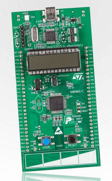
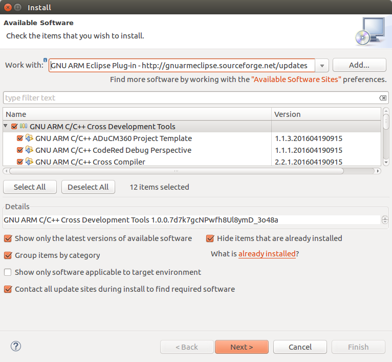
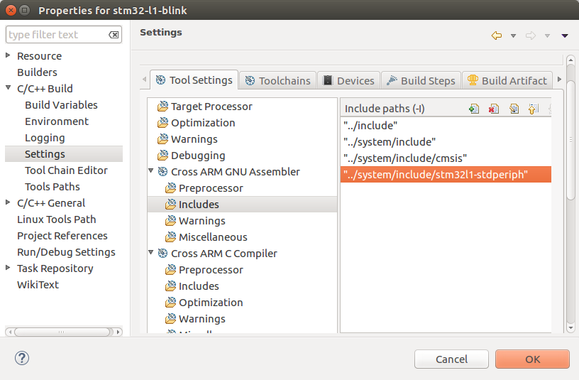
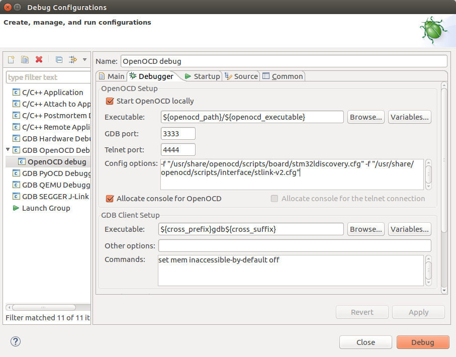
    <content type="html"><![CDATA[<p>ARM microctrollers (MCUs) are cheaper and more powerful than popular Atmel AVR MCUs (<a href="https://habrahabr.ru/post/120611/" target="_blank" rel="noopener">source, Russian</a>). I’m familiar with AVR architecture and I have small experience of work with ATMega, but I want to study usage of ARM MCUs in real applications. If you have some experience in programming and working with some electronics this article may help you to start studying ARM platform.</p><a id="more"></a><p>Advanced RISC Machines Ltd. (ARM) is developing their processor designs which are allowed to license by various hardware manufacturers. ARM <em>does not</em> produce any hardware chips at all! One of the last ARM’s processors is Cortex family. It belongs to ARM v7 architecture and has 3 modifications (profiles):</p><ul><li><em>The A profile</em> is designed for high-performance open application platforms.</li><li><em>The R profile</em> is designed for high-end embedded systems in which real-time performance is needed.</li><li><em>The M profile</em> is designed for deeply embedded microcontroller-type systems.</li></ul><section class="article__side-by-side"><div class="article__side-by-side-cell"><img src="/en/stm32-l152-discovery-toolchain/the-definitive-guide-to-the-arm-cortex-m3-cover-183x226.png" title="The Definitive Guide to the ARM Cortex-M3 cover"></div><div class="article__side-by-side-cell"><p>Cortex-M3 processor is based on one profile of the v7 architecture, called ARM v7-M, an architecture specification for microcontroller products. There’s <a href="/en/stm32-l152-discovery-toolchain/the-definitive-guide-to-the-arm-cortex-m3.pdf" title="“The Definitive Guide to the ARM Cortex-M3” (PDF, 15 MiB)">“The Definitive Guide to the ARM Cortex-M3” (PDF, 15 MiB)</a> — it fits perfetly for those who want to study ARM MCUs’ core.</p></div></section><p>One of ARM’s partners is ST Microelectronics. ST produces a <a href="http://www.st.com/content/st_com/en/products/microcontrollers/stm32-32-bit-arm-cortex-mcus.html" target="_blank" rel="noopener">family of 32-bit MCUs</a>. STM32 F2, STM32 F1 and STM32 L1 series are based on Cortex-M3 core. Like other manufacturers ST surrounds Cortex-M core with a bunch of peripheral circuits giving I/O abilities and various features like timers, ADC, temperature measurement and so on. These peripheral devices are specific to each manufacturer. ST has a range of <a href="http://www.st.com/content/st_com/en/products/evaluation-tools/product-evaluation-tools/mcu-eval-tools/stm32-mcu-eval-tools.html" target="_blank" rel="noopener">tools for evaluation</a> of their MCUs. They’re not very expensive and give you ability to try some of chip’s features without soldering a single wire.</p><section class="article__side-by-side"><div class="article__side-by-side-cell"><p>My friends gave me <a href="http://www.st.com/content/st_com/en/products/evaluation-tools/product-evaluation-tools/mcu-eval-tools/stm32-mcu-eval-tools/stm32-mcu-discovery-kits/32l152cdiscovery.html" target="_blank" rel="noopener">32L152CDISCOVERY</a>—STM32 Discovery kit which has on its board:</p><ul><li>STM32L152RCT6—256 KB Flash memory, 32 KB RAM, 8 KB EEPROM MCU,</li><li>ST-LINK/V2—in-circuit debugger and programmer connected to USB Mini-B socket (most likely your phone uses another plug),</li><li>24-segments LCD,</li><li>touch sensor,</li><li>2 MCU-controlled LEDs,</li><li>1 MCU-connected button.</li></ul></div><div class="article__side-by-side-cell"><img src="/en/stm32-l152-discovery-toolchain/32l152cdiscovery-393x630.jpg" title="32L152CDISCOVERY STM32 Discovery kit"></div></section><p>Last few days I’ve spent trying to configure work with my Discovery board on Ubuntu 16.04. In this article I’ve described set up of the following toolchain:</p><ol><li>Eclipse CDT,</li><li>GNU ARM Eclipse Plug-in,</li><li>GNU ARM Embedded toolchain,</li><li>OpenOCD.</li><li>Open source STLINK tool</li></ol><p>I like this setup so much because it has no proprietary tools in it, I have a full control over each step of board programming and such configuration is pretty common and production-ready.</p><h2 id="Eclipse-CDT"><a href="#Eclipse-CDT" class="headerlink" title="Eclipse CDT"></a>Eclipse CDT</h2><p>If you still haven’t installed Eclipse CDT, do it right now.</p><p>First of all, install Java.</p><figure class="highlight sh"><table><tr><td class="code"><pre><span class="line">sudo apt install openjdk-8-jre</span><br></pre></td></tr></table></figure><p>Download latest Eclipse CDT (Eclipse IDE for C/C++ Developers) from the <a href="https://www.eclipse.org/downloads/eclipse-packages/" target="_blank" rel="noopener">official website</a> and extract it to <code>/opt/</code>. The specific edition used here is Eclipse IDE for C/C++ Developers v. Mars.2 Release (4.5.2).</p><figure class="highlight sh"><table><tr><td class="code"><pre><span class="line"><span class="built_in">cd</span> /opt/ &amp;&amp; sudo tar -zxvf ~/Downloads/eclipse-*.tar.gz</span><br></pre></td></tr></table></figure><p>To make Eclipse available from launcher we should create shortcut (courtesy to <a href="http://ubuntuhandbook.org/index.php/2014/06/install-latest-eclipse-ubuntu-14-04/" target="_blank" rel="noopener">UbuntuHandbook</a> and Ask Ubuntu <a href="http://askubuntu.com/a/371447/398983" target="_blank" rel="noopener">1</a> <a href="http://askubuntu.com/a/761680/398983" target="_blank" rel="noopener">2</a>).</p><figure class="highlight sh"><table><tr><td class="code"><pre><span class="line">gksudo gedit /usr/share/applications/eclipse.desktop</span><br></pre></td></tr></table></figure><p>Paste the following content to the opened file and save it.</p><figure class="highlight ini"><table><tr><td class="code"><pre><span class="line"><span class="section">[Desktop Entry]</span></span><br><span class="line"><span class="attr">Name</span>=Eclipse CDT</span><br><span class="line"><span class="attr">Type</span>=Application</span><br><span class="line"><span class="attr">Exec</span>=env UBUNTU_MENUPROXY=<span class="number">0</span> SWT_GTK3=<span class="number">0</span> /opt/eclipse/eclipse</span><br><span class="line"><span class="attr">Terminal</span>=<span class="literal">false</span></span><br><span class="line"><span class="attr">Icon</span>=/opt/eclipse/icon.xpm</span><br><span class="line"><span class="attr">Comment</span>=Integrated Development Environment</span><br><span class="line"><span class="attr">NoDisplay</span>=<span class="literal">false</span></span><br><span class="line"><span class="attr">Categories</span>=Development<span class="comment">;IDE;</span></span><br><span class="line"><span class="attr">Name[en]</span>=Eclipse CDT</span><br></pre></td></tr></table></figure><p>Now you should be able to open Eclipse from Unity Dash. I’ll assume that you place your Eclipse workspace here: <code>~/workspace/</code></p><p>After that we need to install GNU ARM Plug-in using Eclipse’s internal package manager. To do that go to Help &gt; Install new software. We need to add plugin’s repository to “Work with” field. Press “Add…” button and add “GNU ARM Eclipse Plug-in” repository: <a href="http://gnuarmeclipse.sourceforge.net/updates" target="_blank" rel="noopener">http://gnuarmeclipse.sourceforge.net/updates</a></p><img src="/en/stm32-l152-discovery-toolchain/eclipse-plug-in-installation.png"><h3 id="Useful-keystrokes"><a href="#Useful-keystrokes" class="headerlink" title="Useful keystrokes"></a>Useful keystrokes</h3><ul><li>Ctrl + B — build project,</li><li>F11 — start debugging,</li><li>F8 — resume execution (when program have paused at some breakpoint),</li><li>Ctrl + F2 — stop debugging,</li><li>Ctrl + F8 — switch perspective (from Debug to C/C++ and backwards).</li></ul><h3 id="How-to-make-Eclipse-launch-the-same-debug-configuration-each-time"><a href="#How-to-make-Eclipse-launch-the-same-debug-configuration-each-time" class="headerlink" title="How to make Eclipse launch the same debug configuration each time?"></a>How to make Eclipse launch the same debug configuration each time?</h3><p>You should go to Window &gt; Preferences &gt; Run/Debug &gt; Launching. Select the option “Always launch the previously launched application”. It’s located at the bottom of the dialog. Courtesy to <a href="http://stackoverflow.com/a/2078950/697625" target="_blank" rel="noopener">Stack Overflow</a>.</p><h2 id="GNU-ARM-Embedded-toolchain"><a href="#GNU-ARM-Embedded-toolchain" class="headerlink" title="GNU ARM Embedded toolchain"></a>GNU ARM Embedded toolchain</h2><p>We’re going to compile on our machine MCU’s flash having another processor architecture. This is called cross-compilation. To do that we need special toolchain. Installation is straight-forward for every Ubuntu user.</p><figure class="highlight sh"><table><tr><td class="code"><pre><span class="line">sudo add-apt-repository ppa:team-gcc-arm-embedded/ppa</span><br><span class="line">sudo apt update</span><br><span class="line">sudo apt install gcc-arm-none-eabi gdb-arm-none-eabi</span><br></pre></td></tr></table></figure><p>If installation finished correctly you should be able to test toolchain’s version.</p><figure class="highlight sh"><table><tr><td class="code"><pre><span class="line">arm-none-eabi-gcc --version</span><br></pre></td></tr></table></figure><p>If this command ran correctly, toolchain lays at <code>/usr/bin/</code>. In case when toolchain lays in other place you should specify its location in Eclipse here: Window &gt; Preferences &gt; C/C++ &gt; Build &gt; Global Tools Path.</p><h2 id="OpenOCD"><a href="#OpenOCD" class="headerlink" title="OpenOCD"></a>OpenOCD</h2><p>OpenOCD is a tool for debugging hardware. Ubuntu has pretty fresh OpenOCD v0.9 in its repos now.</p><figure class="highlight sh"><table><tr><td class="code"><pre><span class="line">sudo apt install openocd</span><br></pre></td></tr></table></figure><h2 id="Open-source-STLINK-tool"><a href="#Open-source-STLINK-tool" class="headerlink" title="Open source STLINK tool"></a>Open source STLINK tool</h2><figure class="highlight sh"><table><tr><td class="code"><pre><span class="line"><span class="built_in">cd</span> ~/Downloads/</span><br><span class="line">git <span class="built_in">clone</span> https://github.com/texane/stlink.git</span><br><span class="line"><span class="built_in">cd</span> ~/Downloads/stlink/</span><br><span class="line">sudo install -m 644 etc/udev/rules.d/49-stlinkv2.rules /etc/udev/rules.d/49-stlinkv2.rules</span><br><span class="line">sudo udevadm control --reload-rules</span><br></pre></td></tr></table></figure><h2 id="Create-blinking-“Hello-world”"><a href="#Create-blinking-“Hello-world”" class="headerlink" title="Create blinking “Hello world”"></a>Create blinking “Hello world”</h2><p>In this section we’ll make our board blink with its LED. Eclipse GNU ARM Plug-in has a set of STM32 F-series “hello world” example projects. We need to modify one to test our Discovery board equiepped with STM32 L1-series MCU.</p><p>In Eclipse open File &gt; New &gt; C Project. Choose some Project name (I’ll use <code>stm32-l1-blink</code> name below) and Project type: “STM32F10x C/C++ Project”. The toolchain should be “Cross ARM GCC”. Press “Next”. On the following wizard’s page choose Flash size: 256 kB, RAM size: 32 kB (that’s our STM32L152RCT6 MCU parameters), all other fields leave without changes. Go through the wizard pressing “Next” to the “Finish”.</p><p>Let’s try to build the project to check if toolchain works. Press Project &gt; Build All (Ctrl + B). When compilation finish, you should see <code>Binaries/stm32-l1-blink.elf</code> MCU flash. Compilation works but we should modify the source code.</p><p>“Hello world” generated by Eclipse contains library for working with STM32 F10x peripheral devices. You can download such library for STM32 L1 series from <a href="http://www.st.com/content/st_com/en/products/embedded-software/mcus-embedded-software/stm32-embedded-software/stm32-standard-peripheral-libraries/stsw-stm32077.html" target="_blank" rel="noopener">official website</a> (you’ll need registration) or <a href="/en/stm32-l152-discovery-toolchain/stm32-l1-peripherals-library-v1.3.1.zip" title="my copy">my copy</a> (ZIP, 18 MiB, v1.3.1). Unpack it to “home” (assuming you’ve downloaded it to <code>~/Downloads/</code>):</p><figure class="highlight sh"><table><tr><td class="code"><pre><span class="line">unzip ~/Downloads/stm32-l1-peripherals-library-v1.3.1.zip -d ~</span><br></pre></td></tr></table></figure><p>Peripherals library now unpacked to <code>~/STM32L1xx_StdPeriph_Lib_V1.3.1/</code>. To merge it with our project you should do the following (assuming your Eclipse workspace is at <code>~/workspace/</code>):</p><figure class="highlight sh"><table><tr><td class="code"><pre><span class="line">rm ~/workspace/stm32-l1-blink/include/stm32f10x_conf.h</span><br><span class="line">cp ~/STM32L1xx_StdPeriph_Lib_V1.3.1/Project/STM32L1xx_StdPeriph_Templates/stm32l1xx_conf.h ~/workspace/stm32-l1-blink/include/stm32l1xx_conf.h</span><br><span class="line"></span><br><span class="line">rm ~/workspace/stm32-l1-blink/system/include/cmsis/stm32f10x.h</span><br><span class="line">cp ~/STM32L1xx_StdPeriph_Lib_V1.3.1/Libraries/CMSIS/Device/ST/STM32L1xx/Include/stm32l1xx.h ~/workspace/stm32-l1-blink/system/include/cmsis/stm32l1xx.h</span><br><span class="line"></span><br><span class="line">rm ~/workspace/stm32-l1-blink/system/include/cmsis/system_stm32f10x.h</span><br><span class="line">cp ~/STM32L1xx_StdPeriph_Lib_V1.3.1/Libraries/CMSIS/Device/ST/STM32L1xx/Include/system_stm32l1xx.h ~/workspace/stm32-l1-blink/system/include/cmsis/system_stm32l1xx.h</span><br><span class="line"></span><br><span class="line">rm ~/workspace/stm32-l1-blink/system/src/cmsis/system_stm32f10x.c</span><br><span class="line">cp ~/STM32L1xx_StdPeriph_Lib_V1.3.1/Project/STM32L1xx_StdPeriph_Templates/system_stm32l1xx.c ~/workspace/stm32-l1-blink/system/src/cmsis/system_stm32l1xx.c</span><br><span class="line"></span><br><span class="line">rm -rf ~/workspace/stm32-l1-blink/system/include/stm32f1-stdperiph/</span><br><span class="line">cp -r ~/STM32L1xx_StdPeriph_Lib_V1.3.1/Libraries/STM32L1xx_StdPeriph_Driver/inc/ ~/workspace/stm32-l1-blink/system/include/stm32l1-stdperiph/</span><br><span class="line"></span><br><span class="line">rm -rf ~/workspace/stm32-l1-blink/system/src/stm32f1-stdperiph/</span><br><span class="line">cp -r ~/STM32L1xx_StdPeriph_Lib_V1.3.1/Libraries/STM32L1xx_StdPeriph_Driver/src/ ~/workspace/stm32-l1-blink/system/src/stm32l1-stdperiph/</span><br><span class="line"></span><br><span class="line">cp -rf ~/STM32L1xx_StdPeriph_Lib_V1.3.1/Libraries/CMSIS/Include/ ~/workspace/stm32-l1-blink/system/include/cmsis/</span><br><span class="line"></span><br><span class="line">rm ~/workspace/stm32-l1-blink/system/include/cmsis/core_cm4.h</span><br><span class="line">rm ~/workspace/stm32-l1-blink/system/src/cmsis/vectors_stm32f10x.c</span><br><span class="line">cp ~/STM32L1xx_StdPeriph_Lib_V1.3.1/Libraries/CMSIS/Device/ST/STM32L1xx/Source/Templates/TrueSTUDIO/startup_stm32l1xx_md.s ~/workspace/stm32-l1-blink/system/include/cmsis/startup_stm32l1xx_md.S</span><br></pre></td></tr></table></figure><p>After that go to Project &gt; Properties &gt; C/C++ Build &gt; Settings and point to fresh peripheral library’s “Includes” for Cross ARM GNU Assembler, Cross ARM C Compiler and Cross ARM C++ Compiler: just change directory path from <code>../system/include/stm32f1-stdperiph</code> to <code>../system/include/stm32l1-stdperiph</code></p><img src="/en/stm32-l152-discovery-toolchain/eclipse-build-settings-includes.png"><p>In the same window replace <code>STM32F10X_MD</code> preprocessor definition with <code>STM32L1XX_MD</code>. Do that in “Preprocessor” tabs of Cross ARM GNU Assembler, Cross ARM C Compiler and Cross ARM C++ Compiler.</p><p>We still can’t build the project because of slight differences between STM32 F1 and STM32 L1 peripherals’ libraries.</p><h3 id="include-BlinkLed-h"><a href="#include-BlinkLed-h" class="headerlink" title="include/BlinkLed.h"></a>include/BlinkLed.h</h3><p>Edit include in the header of <code>BlinkLed.h</code>:</p><figure class="highlight c"><table><tr><td class="code"><pre><span class="line"><span class="meta">#<span class="meta-keyword">include</span> <span class="meta-string">"stm32l1xx.h"</span> <span class="comment">// Was `stm32f10x.h`</span></span></span><br></pre></td></tr></table></figure><p>Correct definitions for blue LED on 32L152CDISCOVERY:</p><figure class="highlight c"><table><tr><td class="code"><pre><span class="line"><span class="meta">#<span class="meta-keyword">define</span> BLINK_PORT_NUMBER               (1) <span class="comment">/* Was 2 */</span></span></span><br><span class="line"><span class="meta">#<span class="meta-keyword">define</span> BLINK_PIN_NUMBER                (6) <span class="comment">/* Was 12 */</span></span></span><br><span class="line"><span class="meta">#<span class="meta-keyword">define</span> BLINK_ACTIVE_LOW                (0) <span class="comment">/* Was 1 */</span></span></span><br><span class="line"></span><br><span class="line"><span class="meta">#<span class="meta-keyword">define</span> BLINK_GPIOx(_N)                 ((GPIO_TypeDef *)(GPIOA_BASE + (GPIOB_BASE-GPIOA_BASE)*(_N)))</span></span><br><span class="line"><span class="meta">#<span class="meta-keyword">define</span> BLINK_PIN_MASK(_N)              (1 &lt;&lt; (_N))</span></span><br><span class="line"><span class="meta">#<span class="meta-keyword">define</span> BLINK_RCC_MASKx(_N)             (RCC_AHBPeriph_GPIOA &lt;&lt; (_N)) <span class="comment">/* Used `RCC_APB2Periph_GPIOA` */</span></span></span><br></pre></td></tr></table></figure><h3 id="src-BlinkLed-c"><a href="#src-BlinkLed-c" class="headerlink" title="src/BlinkLed.c"></a>src/BlinkLed.c</h3><p>Edit <code>blink_led_init</code> definition:</p><figure class="highlight c"><table><tr><td class="code"><pre><span class="line"><span class="function"><span class="keyword">void</span> <span class="title">blink_led_init</span><span class="params">()</span></span></span><br><span class="line"><span class="function"></span>&#123;</span><br><span class="line">  <span class="comment">// Enable GPIO Peripheral clock</span></span><br><span class="line">  RCC_AHBPriphClockCmd(BLINK_RCC_MASKx(BLINK_PORT_NUMBER), ENABLE); <span class="comment">// Used `RCC_APB2PeriphClockCmd`</span></span><br><span class="line"></span><br><span class="line">  GPIO_InitTypeDef GPIO_InitStructure;</span><br><span class="line"></span><br><span class="line">  <span class="comment">// Configure pin in output mode</span></span><br><span class="line">  GPIO_InitStructure.GPIO_Pin = BLINK_PIN_MASK(BLINK_PIN_NUMBER);</span><br><span class="line">  GPIO_InitStructure.GPIO_Speed = GPIO_Speed_40MHz; <span class="comment">// Was `GPIO_Speed_50MHz`</span></span><br><span class="line">  GPIO_InitStructure.GPIO_Mode = GPIO_Mode_OUT; <span class="comment">// Was `GPIO_Mode_Out_PP`</span></span><br><span class="line">  GPIO_InitStructure.GPIO_PuPd = GPIO_PuPd_NOPULL; <span class="comment">// New</span></span><br><span class="line">  GPIO_InitStructure.GPIO_OType = GPIO_OType_PP; <span class="comment">// New</span></span><br><span class="line">  GPIO_Init(BLINK_GPIOx(BLINK_PORT_NUMBER), &amp;GPIO_InitStructure);</span><br><span class="line"></span><br><span class="line">  <span class="comment">// Start with led turned off</span></span><br><span class="line">  blink_led_off();</span><br><span class="line">&#125;</span><br></pre></td></tr></table></figure><p>To understand what’s going on in this function read <a href="http://hertaville.com/stm32f0-gpio-tutorial-part-1.html" target="_blank" rel="noopener">article about STM32 F0 GPIO</a>. To understand STM32 L1 GPIO’s peculiarities I encourage you to look at STM32 L1 reference manual. You’re able to <a href="http://www.st.com/resource/en/reference_manual/cd00240193.pdf" target="_blank" rel="noopener">download it</a> from official website or use  (PDF, 13 MiB, v13).</p><h3 id="system-include-cmsis-cmsis-device-h"><a href="#system-include-cmsis-cmsis-device-h" class="headerlink" title="system/include/cmsis/cmsis_device.h"></a>system/include/cmsis/cmsis_device.h</h3><figure class="highlight c"><table><tr><td class="code"><pre><span class="line"><span class="meta">#<span class="meta-keyword">ifndef</span> STM32L1_CMSIS_DEVICE_H_</span></span><br><span class="line"><span class="meta">#<span class="meta-keyword">define</span> STM32L1_CMSIS_DEVICE_H_</span></span><br><span class="line"></span><br><span class="line"><span class="meta">#<span class="meta-keyword">include</span> <span class="meta-string">"stm32l1xx.h"</span></span></span><br><span class="line"></span><br><span class="line"><span class="meta">#<span class="meta-keyword">endif</span> <span class="comment">// STM32L1_CMSIS_DEVICE_H_</span></span></span><br></pre></td></tr></table></figure><p>After this modifications the project can be built without errors.</p><h2 id="Debugging-setup"><a href="#Debugging-setup" class="headerlink" title="Debugging setup"></a>Debugging setup</h2><p>Open Run &gt; Debug Configurations and create new configuration by double-clicking “GDB OpenOCD Debugging”. Rename it as “OpenOCD debug”, choose current project at “Main” tab and configure work with the board in “Config options” field at “Debugger” tab: <code>-f &quot;/usr/share/openocd/scripts/board/stm32ldiscovery.cfg&quot; -f &quot;/usr/share/openocd/scripts/interface/stlink-v2.cfg&quot;</code></p><img src="/en/stm32-l152-discovery-toolchain/eclipse-debug-configuration.png"><p>Now, if you press Debug button your board will be flashed and interactive debug session will be started. You’re able to download <a href="/assets/2016-05-21-stm32-l152-discovery-toolchain/stm32-l1-blink.zip">my stm32-l1-blink project</a> (ZIP, 609 KiB) if any.</p>]]></content>
    
    <summary type="html">
    
      &lt;p&gt;ARM microctrollers (MCUs) are cheaper and more powerful than popular Atmel AVR MCUs (&lt;a href=&quot;https://habrahabr.ru/post/120611/&quot; target=&quot;_blank&quot; rel=&quot;noopener&quot;&gt;source, Russian&lt;/a&gt;). I’m familiar with AVR architecture and I have small experience of work with ATMega, but I want to study usage of ARM MCUs in real applications. If you have some experience in programming and working with some electronics this article may help you to start studying ARM platform.&lt;/p&gt;
    
    </summary>
    
    
      <category term="arm" scheme="https://quasiyoke.me/tags/arm/"/>
    
      <category term="mcu" scheme="https://quasiyoke.me/tags/mcu/"/>
    
      <category term="st" scheme="https://quasiyoke.me/tags/st/"/>
    
      <category term="cortex-m3" scheme="https://quasiyoke.me/tags/cortex-m3/"/>
    
      <category term="gcc" scheme="https://quasiyoke.me/tags/gcc/"/>
    
      <category term="openocd" scheme="https://quasiyoke.me/tags/openocd/"/>
    
      <category term="programming" scheme="https://quasiyoke.me/tags/programming/"/>
    
      <category term="ubuntu" scheme="https://quasiyoke.me/tags/ubuntu/"/>
    
      <category term="eclipse" scheme="https://quasiyoke.me/tags/eclipse/"/>
    
  </entry>
  
  <entry>
    <title>RandTalkBot</title>
    <link href="https://quasiyoke.me/en/randtalkbot/"/>
    <id>https://quasiyoke.me/en/randtalkbot/</id>
    <published>2016-01-04T21:00:00.000Z</published>
    <updated>2021-01-02T01:07:17.983Z</updated>
    
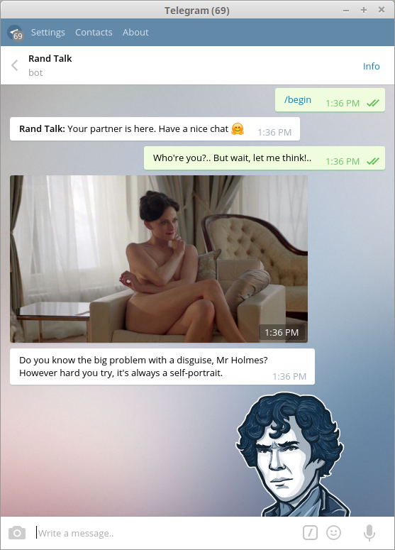
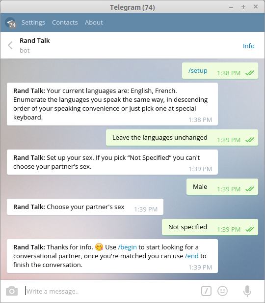
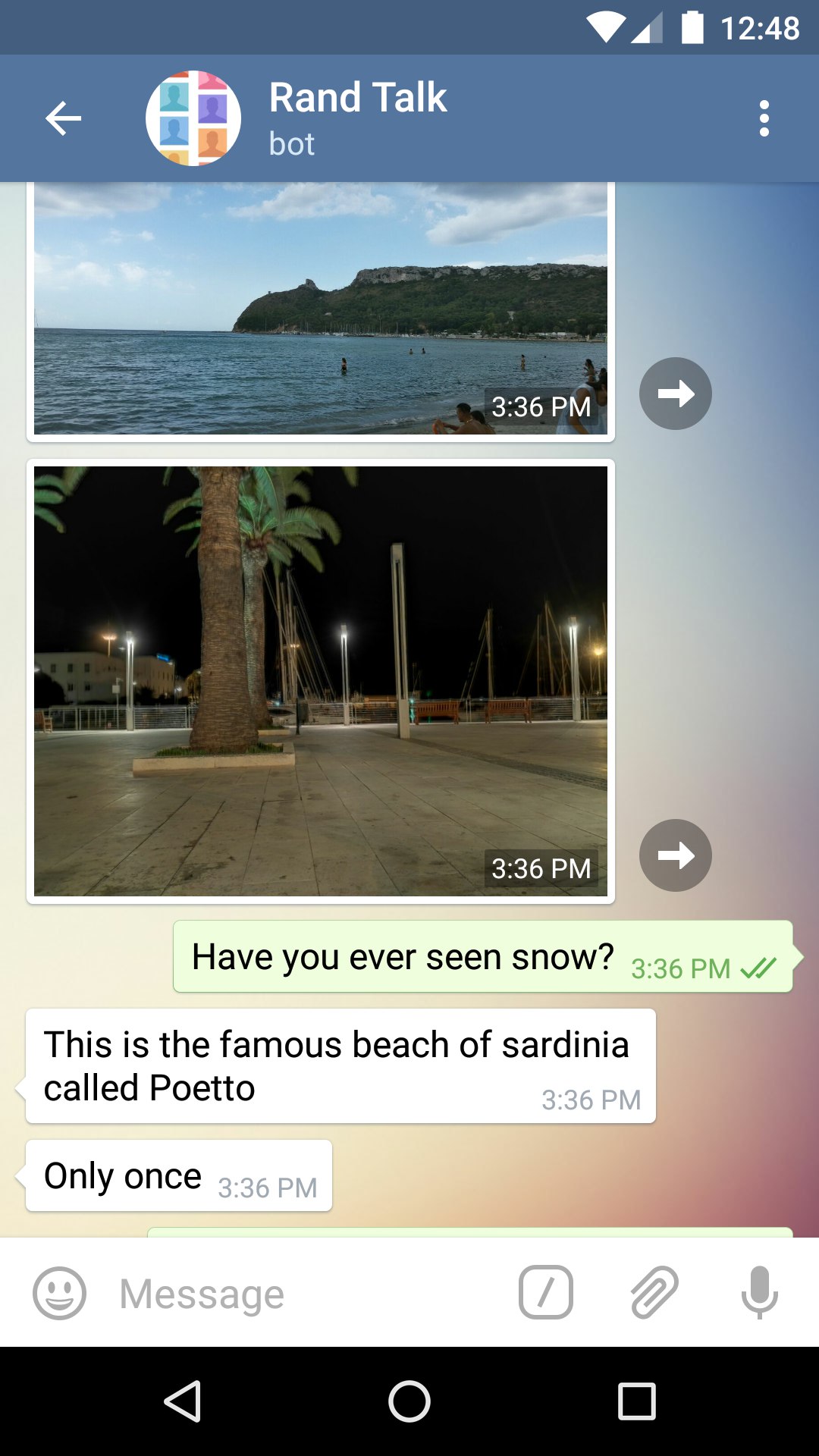
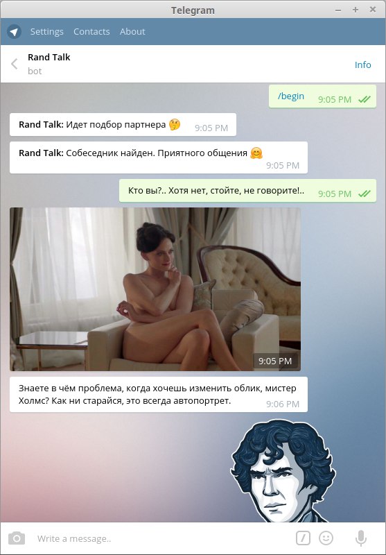
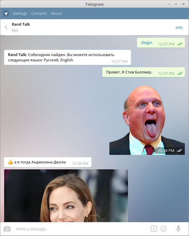
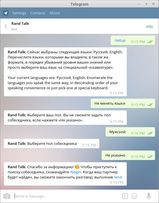
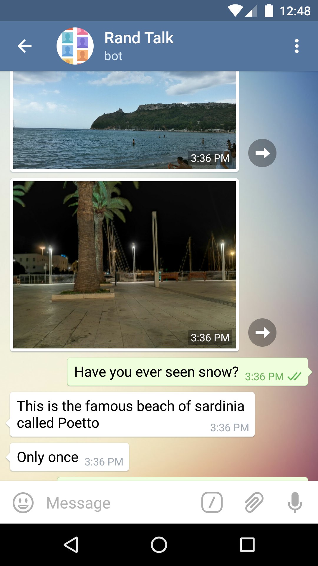
    <content type="html"><![CDATA[<p>Telegram messenger bot connecting you with a&nbsp;random stranger. You’re able to&nbsp;specify sex of&nbsp;the stranger and language to&nbsp;talk.</p><a id="more"></a><img src="/en/randtalkbot/screenshot-holmes.png" title="Chat in Rand Talk: “—Who" alt="re you?.. But wait, let me think!.. —Do you know the big problem with disguise, Mr. Holmes? However hard you try, it"><p>Do you want to talk with somebody, practice in foreign languages or you just want to have some fun? Rand Talk will help you! It’s an anonymous bot matching you with a random stranger of desired sex speaking on your language: <a href="https://t.me/RandTalkBot" target="_blank" rel="noopener">t.me/RandTalkBot</a>.</p><section class="article__side-by-side"><div class="article__side-by-side-cell"><ol><li><p>Choose the language you’d like to talk. Are you know several languages? Enumerate them from your native language to less known, e.g.: “English, Deutsch, Español”. Most of the languages should be specified in English.</p></li><li><p>Choose your sex and your partner’s sex (or don’t specify). The bot is in the lack of women. If you’re a man, you’ll need to wait for a while. The more you wait—the closer you are to the head of the queue.</p></li><li><p>Talk! Attach photos, videos and documents to your messages. The bot supports almost every type of messages except replies and forwarded messages.</p></li></ol></div><div class="article__side-by-side-cell"><img src="/en/randtalkbot/screenshot-setup.png" title="Rand Talk setup"></div></section><section class="article__side-by-side"><div class="article__side-by-side-cell"><img src="/en/randtalkbot/screenshot-snow.jpg" title="Chat in Rand Talk: “—Have you ever seen snow? —Only once”"></div><div class="article__side-by-side-cell"><p>The bot is able to talk with you on English, Russian, German, Spanish or Italian language. If you want to help with Rand Talk’s translation on another languages or you want to participate in development, welcome to the <a href="https://github.com/quasiyoke/RandTalkBot" target="_blank" rel="noopener">GitHub repository</a> (AGPL).</p><p>That’s the first time:</p><ol><li>I’ve written Telegram bot,</li><li>I’ve used Python 3 coroutines at my project,</li><li>I did use unit tests so widely during development.</li></ol><p><a href="https://coveralls.io/github/quasiyoke/RandTalkBot?branch=master" target="_blank" rel="noopener"><img src="https://coveralls.io/repos/github/quasiyoke/RandTalkBot/badge.svg?branch=master" alt="Rand Talk&#39;s Coverage Status"></a></p></div></section><section class="article__side-by-side"><div class="article__side-by-side-cell"><p>During first weeks of work more that 15 thousand people have come to the bot. Most of them speak Italian. English is the second language by popularity. Russian is on the third place. Users are able to send invitational links to their friends. This helps experienced users to invite newbies. To send the invite type in any of your Telegram chats: <code>@RandTalkBot</code> and press <code>Space</code> key: Telegram’s inline query will help you to get your individual invite link in one tap. For every invited user you’ll get bonuses which’ll speed up new partners’ search.</p></div><div class="article__side-by-side-cell"><img src="/en/randtalkbot/screenshot-invite.jpg" title="Rand Talk" alt="s invites"></div></section><p>Unfortunatelly, only 17% of users are women. To fight with such gender inequality Rand Talk gives its bonuses smartly. You’re able to earn 3 bonuses for every “girl” and only 1 for every “boy” you’ll invite. Once Rand Talk will have more females than males, it will switch to generous rewarding you for men automatically.</p><p>I would be glad to meet you at my anonymous chat! <a href="https://t.me/RandTalkBot" target="_blank" rel="noopener">t.me/RandTalkBot</a>.</p>]]></content>
    
    <summary type="html">
    
      &lt;p&gt;Telegram messenger bot connecting you with a&amp;nbsp;random stranger. You’re able to&amp;nbsp;specify sex of&amp;nbsp;the stranger and language to&amp;nbsp;talk.&lt;/p&gt;
    
    </summary>
    
      <category term="Projects" scheme="https://quasiyoke.me/categories/Projects/"/>
    
    
      <category term="python" scheme="https://quasiyoke.me/tags/python/"/>
    
      <category term="telegram" scheme="https://quasiyoke.me/tags/telegram/"/>
    
      <category term="bot" scheme="https://quasiyoke.me/tags/bot/"/>
    
      <category term="chat" scheme="https://quasiyoke.me/tags/chat/"/>
    
  </entry>
  
  <entry>
    <title>RandTalkBot</title>
    <link href="https://quasiyoke.me/ru/randtalkbot/"/>
    <id>https://quasiyoke.me/ru/randtalkbot/</id>
    <published>2016-01-04T21:00:00.000Z</published>
    <updated>2021-01-02T01:07:18.206Z</updated>
    
    <content type="html"><![CDATA[<p>Бот для Телеграма, соединящий вас со&nbsp;случайным собеседником. Вы&nbsp;можете выбрать язык и&nbsp;пол партнёра по&nbsp;чату.</p><a id="more"></a><section class="article__side-by-side"><div class="article__side-by-side-cell"><img src="/ru/randtalkbot/screenshot-holmes.jpg" title="Переписка в Rand Talk: «—Кто вы?.. Хотя нет, стойте, не говорите!.. —Знаете в чём проблема, когда хочешь изменить облик, мистер Холмс? Как ни старайся, это всегда автопортрет.»"></div><div class="article__side-by-side-cell"><img src="/ru/randtalkbot/screenshot-ballmer.jpg" title="Переписка в Rand Talk: «Стив Баллмер» и «Анджелина Джоли»"></div></section><p>Вам нужно общение, хотите отточить иностранный язык или просто повеселиться? На помощь придет Rand Talk—бот для анонимного общения со случайными собеседниками: <a href="https://t.me/RandTalkBot" target="_blank" rel="noopener">t.me/RandTalkBot</a>.</p><section class="article__side-by-side"><div class="article__side-by-side-cell"><ol><li><p>Выберите язык, на котором вы сможете общаться. Знаете несколько языков? Укажите их все—от родного к самым плохо изученным, например так: «Русский, English, Español». Для большинства языков пока нужно использовать их название на английском.</p></li><li><p>Укажите ваш пол и пол собеседника (или не указывайте). Внимание, девушки! У нас дефицит женского населения :) Если вы мужчина, это ничего—когда бот временно не может найти для вас партнера подходящего пола, говорящего с вами на одном языке, он перейдёт в режим ожидания. Чем дольше вы ждете, тем вы ближе к началу очереди—всё честно.</p></li><li><p>Общайтесь: прикрепляйте к сообщениям фотографии, видео, документы. Поддерживаются все типы писем за исключением перенаправленных сообщений.</p></li></ol></div><div class="article__side-by-side-cell"><img src="/ru/randtalkbot/screenshot-setup.jpg" title="Настройки в Rand Talk"></div></section><section class="article__side-by-side"><div class="article__side-by-side-cell"><img src="/ru/randtalkbot/screenshot-snow.jpg" title="Переписка в Rand Talk: «—Have you ever seen snow? —Only once»"></div><div class="article__side-by-side-cell"><p>Бот может разговаривать с вами на русском, английском, немецком, испанском или итальянском. Если вы хотите помочь с переводом Rand Talk’а на другие языки или хотите поучаствовать в разработке, добро пожаловать в <a href="https://github.com/quasiyoke/RandTalkBot" target="_blank" rel="noopener">репу на GitHub</a> (AGPL).</p></div></section><section class="article__side-by-side"><div class="article__side-by-side-cell"><p>За первые несколько недель работы бота в него зашло более 15 тысяч человек. В основном они говоярт по-итальянски и по-английски. Русский—третий по популярности язык. Основная часть новых пользователей узналa о боте благодаря инвайтам—специальным ссылкам, которые рассылали своим контактам старожилы. Чтобы отправить инвайт, наберите в любом своём чате название нашего бота: <code>@RandTalkBot</code> и нажмите пробел—благодаря inline-запросам Telegram вы в один тап отправите ссылку на бот. За каждого приглашенного пользователя вы получите баллы, которые ускорят поиск новых собеседников.</p></div><div class="article__side-by-side-cell"><img src="/ru/randtalkbot/screenshot-invite.jpg" title="Инвайты в Rand Talk"></div></section><p>К сожалению, пока только 17% пользователей—женщины. Для борьбы с гендерным неравенством, бот, начиная с 8-го марта 2016 года, начал автоматически отслеживать соотношение мужчин и женщин. Сейчас за каждую приглашённую девушку вы получите 3 балла, а за мужчин—только 1 балл.</p><p>Буду рад встретить вас в анонимном чате! <a href="https://t.me/RandTalkBot" target="_blank" rel="noopener">t.me/RandTalkBot</a>.</p>]]></content>
    
    <summary type="html">
    
      &lt;p&gt;Бот для Телеграма, соединящий вас со&amp;nbsp;случайным собеседником. Вы&amp;nbsp;можете выбрать язык и&amp;nbsp;пол партнёра по&amp;nbsp;чату.&lt;/p&gt;
    
    </summary>
    
      <category term="Projects" scheme="https://quasiyoke.me/categories/Projects/"/>
    
    
      <category term="python" scheme="https://quasiyoke.me/tags/python/"/>
    
      <category term="telegram" scheme="https://quasiyoke.me/tags/telegram/"/>
    
      <category term="bot" scheme="https://quasiyoke.me/tags/bot/"/>
    
      <category term="chat" scheme="https://quasiyoke.me/tags/chat/"/>
    
  </entry>
  
  <entry>
    <title>Charger</title>
    <link href="https://quasiyoke.me/en/charger/"/>
    <id>https://quasiyoke.me/en/charger/</id>
    <published>2015-08-31T21:00:00.000Z</published>
    <updated>2021-01-02T01:07:17.916Z</updated>
    
    <content type="html"><![CDATA[<p>Arbitrary (Li-ion, NiCd and others) accumulator charger based on&nbsp;switching power supply regulated by&nbsp;ARM microcontroller</p><a id="more"></a><p>I&nbsp;did work on coursework about universal charging device from the September of 2015. I’m developing this device’s modification until now.</p><p>There’re specialized charger controlling chips. Why do I&nbsp;work on my device if anyone can use such chip with only a few mounted passive components? The feature of my project is its <em>universality</em>—it should have ability to change charging accumulator’s type without physical intervention at least in theory.</p><p>Every accumulators’ variety has its own charging regime. For example lead-acid battery is charged by constant voltage, but nickel-cadmium battery—by constant current.</p><section class="article__side-by-side"><div class="article__side-by-side-cell"><img src="/en/charger/avr450.jpg" title="AVR450: Battery Charger for SLA, NiCd, NiMH and Li-Ion Batteries"></div><div class="article__side-by-side-cell"><p>As the basement for my work I’ve used <a href="/en/charger/avr450-battery-charger-for-sla-nicd-liion.pdf" title="AVR450 demo board (PDF, 411 KiB)">AVR450 demo board (PDF, 411 KiB)</a>, regulated by AVR microcontroller AT90S4433. This board is able to charge various accumulators only changing MCU’s flash.</p></div></section><section class="article__side-by-side"><div class="article__side-by-side-cell"><p>You’re able to monitor charging process with AVR450. Using RS232 interface you can see on computer current through the accumulator, voltage on it and accumulator’s temperature. Why such information could be important when you’re charging ordinary accumulator? Li-ion accumulators which I&nbsp;was focused at aren’t as simple as they’re look. For full and fast charging they should pass through two stages:</p><ol><li>constant current charging (I),</li><li>constant voltage charging (U).</li></ol><p>You may see this stages on graph from <a href="/en/charger/radioezhegodnik-2013-vypusk-27.djvu" title="“Annual Radio Journal” 2013, no. 27 (RU, DJVU, 25 MiB)">“Annual Radio Journal” 2013, no. 27 (RU, DJVU, 25 MiB)</a>: at some point we should switch the stages. We want to see on the computer’s screen something like that after Li-ion accumulator charging from zero. We’re interested in stability of desired parameters and in precision of stages’ switching moment.</p></div><div class="article__side-by-side-cell"><img src="/en/charger/liion-charging-stages.png" title="Этапы заряда Li-ion аккумулятора: I—ток, U—напряжение, t—время"></div></section><p>But AVR450’s microcontroller is obsolete at least because it’s hard to find in shops. I&nbsp;have a desire to renovate the scheme using modern ARM-microcontroller STM32L152RBT6. This chip is slightly excess for such charging device, but I&nbsp;want to study modern microcontrollers this way.</p><p>At this moment preliminary device scheme is ready. It still needs to pick up exact resistors’ values, but in general it should stay as is.</p><img src="/en/charger/charger.sch.svg" title="Preliminary charging device scheme"><section class="article__side-by-side"><div class="article__side-by-side-cell"><img src="/en/charger/charger-breadboard.jpg" title="Charger breadboard"></div><div class="article__side-by-side-cell"><p>I’ve used breadboarding with STM32L152 Discovery board actively during the development. This made me sure that the scheme will work when I&nbsp;order expensive PCB.</p></div></section><p>I&nbsp;hope that I’ll extend this post with assembled device photos and final schematic files soon.</p>]]></content>
    
    <summary type="html">
    
      &lt;p&gt;Arbitrary (Li-ion, NiCd and others) accumulator charger based on&amp;nbsp;switching power supply regulated by&amp;nbsp;ARM microcontroller&lt;/p&gt;
    
    </summary>
    
      <category term="Projects" scheme="https://quasiyoke.me/categories/Projects/"/>
    
    
      <category term="arm" scheme="https://quasiyoke.me/tags/arm/"/>
    
      <category term="atmel" scheme="https://quasiyoke.me/tags/atmel/"/>
    
      <category term="mcu" scheme="https://quasiyoke.me/tags/mcu/"/>
    
      <category term="st" scheme="https://quasiyoke.me/tags/st/"/>
    
      <category term="stm32l152rbt6" scheme="https://quasiyoke.me/tags/stm32l152rbt6/"/>
    
      <category term="at90s4433" scheme="https://quasiyoke.me/tags/at90s4433/"/>
    
      <category term="charger" scheme="https://quasiyoke.me/tags/charger/"/>
    
      <category term="li-ion" scheme="https://quasiyoke.me/tags/li-ion/"/>
    
  </entry>
  
  <entry>
    <title>Charger</title>
    <link href="https://quasiyoke.me/ru/charger/"/>
    <id>https://quasiyoke.me/ru/charger/</id>
    <published>2015-08-31T21:00:00.000Z</published>
    <updated>2021-01-02T01:07:18.150Z</updated>
    
    <content type="html"><![CDATA[<p>Универсальный зарядник аккумуляторов на&nbsp;импульсном источнике питания, управляемом ARM-микроконтроллером</p><a id="more"></a><p>С сентября 2015 года я занимался курсовым проектом, целью которого является разработка универсального устройства для заряда различных типов аккумуляторов. Работа над модификацией этого прибора идёт до сих пор.</p><p>Существуют специализированные микросхемы-контроллеры за&shy;ря&shy;да,—и&nbsp;в&nbsp;чём&nbsp;же&nbsp;тог&shy;да пре&shy;лесть моей работы, если можно использовать готовый электронный модуль с&nbsp;минимумом навесных элементов? Особенность моей конструкции в том, что передо мной было поставлено требование <em>универсальности</em> зарядного устройства—чтобы была по крайней мере теоретическая возможность сменить тип заряжаемых аккумуляторов, не внося физических изменений в устройство.</p><p>Каждая разновидность аккумуляторов заряжается в отличном от других режиме. К&nbsp;примеру, свинцовые аккумуляторы нужно заряжать постоянным напряжением, а&nbsp;вот никель-кадмиевые (NiCd)—постоянным током.</p><section class="article__side-by-side"><div class="article__side-by-side-cell"><img src="/ru/charger/avr450.jpg" title="AVR450: Battery Charger for SLA, NiCd, NiMH and Li-Ion Batteries"></div><div class="article__side-by-side-cell"><p>В основу моей конструкции легла <a href="/ru/charger/avr450-battery-charger-for-sla-nicd-liion.pdf" title="демонстрационная плата AVR450 (PDF, 411 KiB)">демонстрационная плата AVR450 (PDF, 411 KiB)</a>, использующая микроконтроллер AVR AT90S4433. Эта плата позволяет осуществлять зарядку аккумуляторов различных типов, не меняя ничего кроме прошивки микроконтроллера.</p></div></section><section class="article__side-by-side"><div class="article__side-by-side-cell"><p>AVR450 даёт возможность следить за процессом заряда. Если подключить модуль к&nbsp;компьютеру по интерфейсу RS232, можно пронаблюдать за током через аккумулятор, отслеживать напряжение на нём и температуру его корпуса. Казалось бы, что интересного можно увидеть, если записать эти показатели у обычного аккумулятора? Оказывается, Li-ion аккумуляторы, на которых было принято решение сфокусироваться, не так просты. Для быстрой и полной их зарядки требуется пройти через два этапа:</p><ol><li>зарядка постоянным током (I),</li><li>зарядка постоянным напряжением (U).</li></ol><p>На графике из <a href="/ru/charger/radioezhegodnik-2013-vypusk-27.djvu" title="Радиоежегодника от 2013 года, выпуск 27 (DJVU, 25 MiB)">Радиоежегодника от 2013 года, выпуск 27 (DJVU, 25 MiB)</a> наглядно показаны эти процессы: как от первого этапа мы переходим ко второму. Зарядив Li&#x2011;ion аккумулятор с нуля и собрав показания с AVR450, хотелось бы увидеть на&nbsp;экране компьютера что-то подобное. В&nbsp;реальной жизни представляет интерес постоянство нужных показателей и точность соблюдения требуемого момента смены этапов.</p></div><div class="article__side-by-side-cell"><img src="/ru/charger/liion-charging-stages.png" title="Этапы заряда Li-ion аккумулятора: I—ток, U—напряжение, t—время"></div></section><p>Однако микроконтроллер, использованный в AVR450, устарел хотя бы потому, что его уже трудно найти в продаже. У меня возникло желание модернизировать схему, использовав в ней современный ARM-микроконтроллер STM32L152RBT6. Эта микросхема несколько избыточна для относительно несложного зарядного устройства, но мне очень хотелось попутно научиться работать с современными микроконтроллерами.</p><p>На настоящий момент готова предварительная принципиальная схема зарядного устройства. В ней ещё требуется подобрать номиналы резисторов обратной связи операционных усилителей, но в общих чертах она измениться не должна.</p><img src="/ru/charger/charger.sch.svg" title="Предварительный вариант схемы электрической принципиальной зарядного устройства"><section class="article__side-by-side"><div class="article__side-by-side-cell"><img src="/ru/charger/charger-breadboard.jpg" title="Макет зарядного устройства"></div><div class="article__side-by-side-cell"><p>В процессе разработки я активно применял макетирование с использованием платы STM32L152 Discovery и заранее купленных деталей, предназначенных для установки в реальную схему. Это вселяло в меня уверенность, что устройство заработает, когда уже будет заказана дорогостоящая печатная плата.</p></div></section><p>Надеюсь, что в скором времени я дополню этот пост фотографиями изготовленного устройства и конечными чертежами.</p>]]></content>
    
    <summary type="html">
    
      &lt;p&gt;Универсальный зарядник аккумуляторов на&amp;nbsp;импульсном источнике питания, управляемом ARM-микроконтроллером&lt;/p&gt;
    
    </summary>
    
      <category term="Projects" scheme="https://quasiyoke.me/categories/Projects/"/>
    
    
      <category term="arm" scheme="https://quasiyoke.me/tags/arm/"/>
    
      <category term="atmel" scheme="https://quasiyoke.me/tags/atmel/"/>
    
      <category term="mcu" scheme="https://quasiyoke.me/tags/mcu/"/>
    
      <category term="st" scheme="https://quasiyoke.me/tags/st/"/>
    
      <category term="stm32l152rbt6" scheme="https://quasiyoke.me/tags/stm32l152rbt6/"/>
    
      <category term="at90s4433" scheme="https://quasiyoke.me/tags/at90s4433/"/>
    
      <category term="charger" scheme="https://quasiyoke.me/tags/charger/"/>
    
      <category term="li-ion" scheme="https://quasiyoke.me/tags/li-ion/"/>
    
  </entry>
  
  <entry>
    <title>InstaBot</title>
    <link href="https://quasiyoke.me/en/instabot/"/>
    <id>https://quasiyoke.me/en/instabot/</id>
    <published>2015-06-06T21:00:00.000Z</published>
    <updated>2021-01-02T01:07:17.916Z</updated>
    
    <content type="html"><![CDATA[<p>The bot for increasing your Instagram audience by&nbsp;following people and unfollowing them after specified period of&nbsp;time&nbsp;;)</p><a id="more"></a><p><a href="https://github.com/quasiyoke/InstaBot" target="_blank" rel="noopener">Instagram bot</a> written in&nbsp;Python 3.5 that cycles through specified hashtags and automatically likes pictures with those hashtags to&nbsp;get more followers. The bot also follows people and unfollows them after specified period of&nbsp;time. Unfollowed people are saved in&nbsp;DB&nbsp;to&nbsp;prevent following them again. To&nbsp;find new people to&nbsp;follow it&nbsp;uses list of&nbsp;followers of&nbsp;people you have followed.</p><p>During installation process it saves people followed by you as “followed long time ago” and unfollows them at the first start.</p><p>The bot doesn’t use Instagram API so all credentials you need are your login and password.</p><p>I’ve forked this bot from the <a href="https://github.com/marclave/InstaBot" target="_blank" rel="noopener">Marc Laventure’s repository</a>. It was rewritten significantly: Python version was raised up and lots of new features were added.</p><h2 id="Deployment"><a href="#Deployment" class="headerlink" title="Deployment"></a>Deployment</h2><pre><code>$ virtualenv --python=/usr/bin/python3 instabotenv$ cd instabotenv$ source bin/activate(instabotenv) $ git clone https://github.com/quasiyoke/InstaBot.git(instabotenv) $ cd InstaBot(instabotenv) $ pip install -r requirements.txt</code></pre><p>Create MySQL DB:</p><figure class="highlight sql"><table><tr><td class="code"><pre><span class="line"><span class="keyword">CREATE</span> <span class="keyword">DATABASE</span> <span class="keyword">IF</span> <span class="keyword">NOT</span> <span class="keyword">EXISTS</span> instagram <span class="built_in">CHARACTER</span> <span class="keyword">SET</span> utf8 <span class="keyword">COLLATE</span> utf8_general_ci;</span><br><span class="line"><span class="keyword">CREATE</span> <span class="keyword">USER</span> instabot@localhost <span class="keyword">IDENTIFIED</span> <span class="keyword">BY</span> <span class="string">'GT8H!b]5,9&#125;A7'</span>;</span><br><span class="line"><span class="keyword">GRANT</span> <span class="keyword">ALL</span> <span class="keyword">ON</span> instagram.* <span class="keyword">TO</span> instabot@localhost;</span><br></pre></td></tr></table></figure><p>Create <code>configuration.yml</code> file containing your credentials, e.g.:</p><figure class="highlight yaml"><table><tr><td class="code"><pre><span class="line"><span class="attr">credentials:</span></span><br><span class="line">  <span class="attr">username:</span> <span class="string">"your_username"</span></span><br><span class="line">  <span class="attr">password:</span> <span class="string">"eKeFB2;AW6fS&#125;z"</span></span><br><span class="line"><span class="attr">db:</span></span><br><span class="line">  <span class="attr">host:</span> <span class="string">"localhost"</span></span><br><span class="line">  <span class="attr">name:</span> <span class="string">"instagram"</span></span><br><span class="line">  <span class="attr">user:</span> <span class="string">"instabot"</span></span><br><span class="line">  <span class="attr">password:</span> <span class="string">"GT8H!b]5,9&#125;A7"</span></span><br><span class="line"><span class="attr">following_hours:</span> <span class="number">120</span></span><br><span class="line"><span class="attr">hashtags:</span></span><br><span class="line">  <span class="bullet">-</span> <span class="string">I</span></span><br><span class="line">  <span class="bullet">-</span> <span class="string">люблю</span></span><br><span class="line">  <span class="bullet">-</span> <span class="string">Python</span></span><br><span class="line"><span class="attr">instagram:</span></span><br><span class="line">  <span class="attr">limit_sleep_time_coefficient:</span> <span class="number">1.3</span></span><br><span class="line">  <span class="attr">limit_sleep_time_min:</span> <span class="number">30</span></span><br><span class="line">  <span class="attr">success_sleep_time_coefficient:</span> <span class="number">0.5</span></span><br><span class="line">  <span class="attr">success_sleep_time_max:</span> <span class="number">6</span></span><br><span class="line">  <span class="attr">success_sleep_time_min:</span> <span class="number">4</span></span><br><span class="line"><span class="attr">logging:</span></span><br><span class="line">  <span class="attr">version:</span> <span class="number">1</span></span><br><span class="line">  <span class="attr">formatters:</span></span><br><span class="line">    <span class="attr">simple:</span></span><br><span class="line">      <span class="attr">class:</span> <span class="string">logging.Formatter</span></span><br><span class="line">      <span class="attr">format:</span> <span class="string">"%(asctime)s - %(levelname)s - %(name)s - %(message)s"</span></span><br><span class="line">  <span class="attr">handlers:</span></span><br><span class="line">    <span class="attr">console:</span></span><br><span class="line">      <span class="attr">class:</span> <span class="string">logging.StreamHandler</span></span><br><span class="line">      <span class="attr">level:</span> <span class="string">DEBUG</span></span><br><span class="line">      <span class="attr">formatter:</span> <span class="string">simple</span></span><br><span class="line">    <span class="attr">file:</span></span><br><span class="line">      <span class="attr">class:</span> <span class="string">logging.handlers.RotatingFileHandler</span></span><br><span class="line">      <span class="attr">level:</span> <span class="string">DEBUG</span></span><br><span class="line">      <span class="attr">formatter:</span> <span class="string">simple</span></span><br><span class="line">      <span class="attr">filename:</span> <span class="string">log.log</span></span><br><span class="line">      <span class="attr">maxBytes:</span> <span class="number">10485760</span></span><br><span class="line">      <span class="attr">backupCount:</span> <span class="number">10</span></span><br><span class="line">      <span class="attr">encoding:</span> <span class="string">utf-8</span></span><br><span class="line">  <span class="attr">loggers:</span></span><br><span class="line">    <span class="attr">instabot:</span></span><br><span class="line">      <span class="attr">level:</span> <span class="string">DEBUG</span></span><br><span class="line">  <span class="attr">root:</span></span><br><span class="line">    <span class="attr">level:</span> <span class="string">DEBUG</span></span><br><span class="line">    <span class="attr">handlers:</span></span><br><span class="line">      <span class="bullet">-</span> <span class="string">console</span></span><br><span class="line"><span class="attr">users_to_follow_cache_size:</span> <span class="number">300</span></span><br></pre></td></tr></table></figure><p>Where:</p><ul><li><code>following_hours</code>—how long users will stay followed.</li><li><code>hashtags</code>—list of hashtags to get photos to like. Optional. By default bot won’t like anything.</li><li><code>logging</code>—logging setup as described in <a href="https://docs.python.org/3/howto/logging.html" target="_blank" rel="noopener">this howto</a>.</li><li><code>users_to_follow_cache_size</code>—how much users should be fetched for following. The cache is being filled in once a minute. Optional. By default bot won’t follow anybody.</li></ul><p>Create necessary DB tables:</p><pre><code>(instabotenv) $ ./instabot_runner.py install configuration.yml</code></pre><p>Run:</p><pre><code>(instabotenv) $ ./instabot_runner.py configuration.yml</code></pre>]]></content>
    
    <summary type="html">
    
      &lt;p&gt;The bot for increasing your Instagram audience by&amp;nbsp;following people and unfollowing them after specified period of&amp;nbsp;time&amp;nbsp;;)&lt;/p&gt;
    
    </summary>
    
      <category term="Projects" scheme="https://quasiyoke.me/categories/Projects/"/>
    
    
      <category term="python" scheme="https://quasiyoke.me/tags/python/"/>
    
      <category term="instagram" scheme="https://quasiyoke.me/tags/instagram/"/>
    
  </entry>
  
  <entry>
    <title>Add to Feedly Plus</title>
    <link href="https://quasiyoke.me/en/add-to-feedly-plus/"/>
    <id>https://quasiyoke.me/en/add-to-feedly-plus/</id>
    <published>2014-11-15T21:00:00.000Z</published>
    <updated>2021-01-02T01:07:17.906Z</updated>
    
    <content type="html"><![CDATA[<p>Firefox browser extension allowing you to quickly add RSS feeds to Feedly reader. Its peak daily users count was about 2.6 thousand people.</p><a id="more"></a><p><a href="https://feedly.com/" target="_blank" rel="noopener">Feedly</a> is a web RSS reader. It gives you ability to comfortably read news from any source you like. RSS is widely supported by various websites. You can receive updates from this site <a href="/atom.xml">using RSS</a> too!</p><section class="article__side-by-side"><div class="article__side-by-side-cell"><img src="/en/add-to-feedly-plus/screenshot-inactive.png" title="Add to Feedly Plus inactive screenshot"></div><div class="article__side-by-side-cell"><p><a href="https://addons.mozilla.org/en-US/firefox/addon/add-to-feedly-plus/" target="_blank" rel="noopener">My Firefox extension</a> indicates if the website you browse has RSS feed. If it hasn’t the extension doesn’t bother you (it looks like gray inactive Feedly icon). But if the site has RSS you can instantly add it to the Feedly with several clicks.<br></p></div></section><p></p><section class="article__side-by-side"><div class="article__side-by-side-cell"><p>I’ve started this project with forking <a href="https://addons.mozilla.org/en-US/firefox/addon/add-to-feedly/" target="_blank" rel="noopener">original Add to Feedly extension</a>. Saeed Moqadam have written very simple and great extension but it lacks some features I want. Some websites have several RSS feeds simultaneously. In such cases they usually provide short description of each feed. This information is very simple to extract from the webpage. I did it and called my fork “Add to Feedly Plus”.</p></div><div class="article__side-by-side-cell"><img src="/en/add-to-feedly-plus/screenshot-menu.png" title="Add to Feedly Plus menu screenshot"></div></section><p>Despite from its simplicity, my addon was unexpectedly popular at Mozilla Firefox extensions’ catalog. At its peak daily users count was around 2.6 thousand people. It’s first so popular program written by me.</p><p>Audience of my extension is decreasing. You’re able to look at the stats <a href="https://addons.mozilla.org/en-US/firefox/addon/add-to-feedly-plus/statistics/?last=365" target="_blank" rel="noopener">here</a>. Perhaps I’ll try do something with it in the future.</p><img src="/en/add-to-feedly-plus/audience.png" title="Add to Feedly Plus stats"><p>I was very pleased by <a href="https://github.com/quasiyoke/add-to-feedly-plus/pull/1" target="_blank" rel="noopener">Yufan Lou’s pull request</a> extending the list of supported RSS MIME types (courtesy of <a href="https://stackoverflow.com/a/7001617/2449800" target="_blank" rel="noopener">Robert MacLean</a>). Now Add to Feedly Plus supports the following full (I hope) list of RSS MIME types:</p><figure class="highlight plain"><table><tr><td class="code"><pre><span class="line">application/rss+xml</span><br><span class="line">application/rdf+xml</span><br><span class="line">application/atom+xml</span><br><span class="line">application/xml</span><br><span class="line">text/xml</span><br></pre></td></tr></table></figure><p>You’re welcome to <a href="https://addons.mozilla.org/en-US/firefox/addon/add-to-feedly-plus/" target="_blank" rel="noopener">install my addon</a> or to view its <a href="https://github.com/quasiyoke/add-to-feedly-plus" target="_blank" rel="noopener">source code at GitHub</a>.</p>]]></content>
    
    <summary type="html">
    
      &lt;p&gt;Firefox browser extension allowing you to quickly add RSS feeds to Feedly reader. Its peak daily users count was about 2.6 thousand people.&lt;/p&gt;
    
    </summary>
    
      <category term="Projects" scheme="https://quasiyoke.me/categories/Projects/"/>
    
    
      <category term="javascript" scheme="https://quasiyoke.me/tags/javascript/"/>
    
      <category term="feedly" scheme="https://quasiyoke.me/tags/feedly/"/>
    
      <category term="firefox" scheme="https://quasiyoke.me/tags/firefox/"/>
    
      <category term="rss" scheme="https://quasiyoke.me/tags/rss/"/>
    
  </entry>
  
  <entry>
    <title>Nixie-часы</title>
    <link href="https://quasiyoke.me/ru/nixie-clock/"/>
    <id>https://quasiyoke.me/ru/nixie-clock/</id>
    <published>2014-10-23T20:00:00.000Z</published>
    <updated>2021-01-02T01:07:18.146Z</updated>
    
    <content type="html"><![CDATA[<p>Электронные часы с&nbsp;газоразрядными индикаторами и&nbsp;автоконтролем яркости цифр на&nbsp;ARM-микроконтроллере</p><a id="more"></a><p>По всему миру любители собирают электронные часы, в которых для вывода информации (отображения цифр) используются «многоэлектродные индикаторы тлеющего разряда» или т.н. «газоразрядные индикаторы». По-английски эти радиолампы зовут «nixie tubes», а часы на такой элементной базе: «nixie clock». В&nbsp;популярности этого увлечения легко убедиться, <a href="https://www.google.com/search?q=nixie+clock&amp;tbm=isch" target="_blank" rel="noopener">поискав «nixie clock» картинки</a>. Интересная особенность большинства таких часов—использование, можно сказать, морально устаревших индикаторов (разумеется, из эстетических соображений) совместно с современными цифровыми микросхемами. По&#x2011;моему прекрасная мода, в гонке за которой я с удовольствием участвую.</p><img src="/ru/nixie-clock/nixie-clock-search.jpg" title="Поиск картинок по запросу «nixie clock»"><section class="article__side-by-side"><div class="article__side-by-side-cell"><img src="/ru/nixie-clock/in12.png" title="Габаритные размеры газоразрядного индикатора ИН-12А"></div><div class="article__side-by-side-cell"><p>У меня есть шесть газоразрядных индикаторов ИН-12А. Их достаточно подробные характеристики можно найти в справочнике «Электровакуумные, электронные и&nbsp;газоразрядные приборы» под редакцией А.С.&nbsp;Ларионова, с.&nbsp;514.</p><p>Важное свойство большинства радиоламп вообще—необходимость в источнике высокого напряжения. К примеру, мои ИН-12А гарантированно зажигаются при напряжении 170&nbsp;В. Разумеется, это совсем не тысячи вольт анодного напряжения какого-нибудь кинескопа, но уверяю вас, что этого несколько раз хватит для пробоя типичного цифрового компонента.</p></div></section><p>Если вы соберётесь делать такие часы, первую половину проблем вам создаст цифровая часть (например, программирование микроконтроллера), а вторую—капризная схема источника высокого напряжения. Такой источник отвечает за&nbsp;повышение напряжения, на пример, с 12&nbsp;В до требуемых 170&nbsp;В. Будьте готовы для него:</p><ol><li>искать где-то катушку с не только заданной индуктивностью (сотни микрогенри), но&nbsp;и&nbsp;током насыщения (около 1&nbsp;А),</li><li>покупать дорогие полевые транзисторы, которые будут норовить сгореть,</li><li>внимательно следить при макетировании не только за тем, чтобы не было лишних контактов, но и за наличием всех необходимых соединений—здесь это часто служит причиной порчи деталей,</li><li>налаживать схему, постоянно остерегаясь удара высоким напряжением.</li></ol><section class="article__side-by-side"><div class="article__side-by-side-cell"><p>Приведённый здесь фрагмент <a href="http://radioskot.ru/publ/byttekhnika/svetjashhiesja_chasy/21-1-0-649" target="_blank" rel="noopener">схемы Sunny Clock</a> на микросхеме MC34063AD, которая дала толчок моим изысканиям, принимает 12&nbsp;В в узле <code>P12V</code> и генерирует высокое анодное напряжение в узле <code>HV</code>. Поначалу я думал в точности повторить этот модуль в своей конструкции, однако оказалось, что полевой транзистор Q1 ощутимо нагревается в процессе работы без каких-либо разумных для того оснований. Судя по&nbsp;всему, многих повторивших эту схему устраивает такое поведение, поскольку нагрев не очень существенный, однако некоторый перфекционизм во мне сопротивлялся таким компромиссам.</p></div><div class="article__side-by-side-cell"><img src="/ru/nixie-clock/sunny-clock-power-supply.png" title="Высоковольтный источник питания конструкции Sunny Clock"></div></section><p>Благодаря <a href="https://threeneurons.wordpress.com/nixie-power-supply/" target="_blank" rel="noopener">одному материалу</a> я узнал, что у MC34063AD есть возможность только «подтягивать» затвор транзистора Q1 к +12&nbsp;В и&nbsp;нет возможности задать ему нулевой потенциал. Поскольку для полевых транзисторов характерна некоторая ёмкость затвора, для того, чтобы полевик закрылся, требуется резистор R12—это через него разряжается затвор. Сие решение, конечно, ущербно, поскольку во время переходного процесса по разрядке затвора транзистор находится в линейном режиме, и на нём выделяется тепло. Из той же статьи я почерпнул грамотное решение этой проблемы с&nbsp;использованием дополнительного PNP-транзистора (Q2 на&nbsp;моей схеме ниже), которое хорошо показало себя на практике.</p><section class="article__side-by-side"><div class="article__side-by-side-cell"><img src="/ru/nixie-clock/decoder-breadboard.jpg" title="Испытание дешифратора К155ИД1 на макетной плате"></div><div class="article__side-by-side-cell"><p>Для управления устрашающими сотнями вольт с помощью хиленького микроконтроллера можно использовать десяток достаточно высоковольтных транзисторов, либо специализированную <a href="http://www.chipinfo.ru/dsheets/ic/155/id1.html" target="_blank" rel="noopener">микросхему К155ИД1</a>, как это сделал я. Она также содержит дешифратор, что сэкономит порты микроконтроллера.</p><p>На фото вы можете видеть процесс испытания дешифратора. На макетную плату поданы два напряжения: +180 В—для питания индикатора и +5 В—для микросхемы. Для задания нужного двоичного кода достаточно «занулить» требуемые ножки дешифратора: TTL-логика означает, что все неприсоединённые ножки будут «подключены» к высокому уровню сами по себе.<br></p></div></section><p></p><p>Ниже приведена слегка модифицированная схема Sunny Clock, которая мной не&nbsp;испытывалась.</p><img src="/ru/nixie-clock/nixie-clock.sch.svg" title="Вариант конструкции nixie-часов на ATMega8"><p>У этой конструкции есть существенные недостатки.</p><ol><li><p>Из схемы этого явно не видно, но я изначально предполагал распределить три анодных оптопары по цифрам следующим образом: <code>12:31:23</code>—такое распределение означает, что для того, чтобы погасить оба разряда минут, к примеру, придётся подать высокое напряжение на все катоды соответствующих ламп. Оказывается, как замечают на уже упоминавшемся выше <a href="https://threeneurons.wordpress.com/nixie-power-supply/" target="_blank" rel="noopener">сайте</a>, гасить индикаторы таким образом не рекомендуется:</p><blockquote><p><em>Do not</em> blank, by turning all cathodes <em>off</em>. Especially, when using cathode drivers like a 74141 (or its Russian equivalent). If you attempt this with these devices, they will see over ~100V, and will conduct thru more than one cathode at a time. This will look similar to ghosting. These devices are leaky, so at least one cathode should be ON at all times.</p></blockquote><p>Чтобы иметь возможность погасить на мгновение нужную пару ламп, составляющих число, следует распределить оптопары по индикаторам следующим образом: <code>11:22:33</code>—значит чтобы погасить, к примеру, минуты, вы можете просто снять анодное напряжение оптопарой номер 2. Это пригодится, например, для режима настройки часов, чтобы мигать настраиваемым числом: часами, минутами или секундами.</p></li><li><p>Схема использует морально устаревший микроконтроллер ATMega8. В рамках моей постоянной программы по изучению ARM, я бы хотел использовать в своих часах STM32L152RBT6.</p></li><li><p>Микроконтроллер вполне может взять на себя функции микросхемы MC34063AD. Все микроконтроллеры обладают широкими возможностями по генерации ШИМ-сигналов и АЦП, подходящим для создания отрицательной обратной связи, следящей за уровнем высокого напряжения. Тем самым мы не только избавляемся от лишнего корпуса, но и получаем возможность без труда интеллектуально менять анодное напряжение на индикаторах—к примеру, в зависимости от условий освещения.</p></li></ol><p>В скором будущем эта статья, надеюсь, будет дополнена фотографиями прототипа.</p>]]></content>
    
    <summary type="html">
    
      &lt;p&gt;Электронные часы с&amp;nbsp;газоразрядными индикаторами и&amp;nbsp;автоконтролем яркости цифр на&amp;nbsp;ARM-микроконтроллере&lt;/p&gt;
    
    </summary>
    
      <category term="Projects" scheme="https://quasiyoke.me/categories/Projects/"/>
    
    
      <category term="arm" scheme="https://quasiyoke.me/tags/arm/"/>
    
      <category term="atmega8" scheme="https://quasiyoke.me/tags/atmega8/"/>
    
      <category term="atmel" scheme="https://quasiyoke.me/tags/atmel/"/>
    
      <category term="clock" scheme="https://quasiyoke.me/tags/clock/"/>
    
      <category term="mcu" scheme="https://quasiyoke.me/tags/mcu/"/>
    
      <category term="nixie" scheme="https://quasiyoke.me/tags/nixie/"/>
    
      <category term="st" scheme="https://quasiyoke.me/tags/st/"/>
    
      <category term="stm32l152rbt6" scheme="https://quasiyoke.me/tags/stm32l152rbt6/"/>
    
  </entry>
  
  <entry>
    <title>Nixie Clock</title>
    <link href="https://quasiyoke.me/en/nixie-clock/"/>
    <id>https://quasiyoke.me/en/nixie-clock/</id>
    <published>2014-10-23T20:00:00.000Z</published>
    <updated>2021-01-02T01:07:17.900Z</updated>
    
    <content type="html"><![CDATA[<p>Unusual steampunk-themed clock with orange glowing cold cathode display and automatic brightness control based on&nbsp;ARM microcontroller</p><a id="more"></a><p>Amateurs around the world are building electronic clock using “cold cathode display” or&nbsp;”nixie” tubes for displaying digits. Such clock are usually called nixie clock. If you <a href="https://www.google.com/search?q=nixie+clock&amp;tbm=isch" target="_blank" rel="noopener">search for “nixie clock” pictures</a> you’ll see how popular they are. Interesting nixie clock feature is that they’re using obsolete indicators (for aesthetic purpose of course) but modern chips. I think this trend is charming and I’m happy to participate in it.</p><img src="/en/nixie-clock/nixie-clock-search.jpg" title="Search for “nixie clock” pictures"><section class="article__side-by-side"><div class="article__side-by-side-cell"><img src="/en/nixie-clock/in12.png" title="Size of IN-12A nixie tube"></div><div class="article__side-by-side-cell"><p>I have six IN12-A nixie tubes. You may find their properties at some reference.</p><p>Important radio valves’ requirement is high anode voltage. My&nbsp;IN12-A tubes are shining reliably at&nbsp;170&nbsp;V. Of&nbsp;course that’s far from thousands of volts for some CRT, but such voltage can kill typical digital component several times at once.</p></div></section><p>If you’re building such clock first part of your troubles will be produced by digital circuit (flashing your MCU for example) and second part by cranky high voltage generator. Such power source is responsible for stepping up voltage from e.g. 12&nbsp;V to&nbsp;desirable 170&nbsp;V. You should be&nbsp;ready&nbsp;to:</p><ol><li>find somewhere coil with specified inductivity (hundreds of microhenry) and saturation current (approximately 1&nbsp;A),</li><li>buy expensive field-effect transistors which will tend to burn out,</li><li>look for redundant and missing contacts between the parts carefully, the latter are risky in such schemes too,</li><li>debug the scheme bewaring of high voltage strokes continuously.</li></ol><section class="article__side-by-side"><div class="article__side-by-side-cell"><p>The following <a href="http://radioskot.ru/publ/byttekhnika/svetjashhiesja_chasy/21-1-0-649" target="_blank" rel="noopener">Sunny Clock scheme (ru)</a> fragment based on MC34063AD chip was the starter for my discoveries. It&nbsp;takes 12&nbsp;V at <code>P12V</code> node and generates high anode voltage at&nbsp;<code>HV</code> node. At first I’ve tried to reproduce this module as is but it turned out that transistor Q1 is pretty hot without any rational reason. It looks like most of&nbsp;amateurs are OK with such behavior because this heating isn’t significant but I wasn’t satisfied with this compromise.</p></div><div class="article__side-by-side-cell"><img src="/en/nixie-clock/sunny-clock-power-supply.png" title="Sunny Clock" alt="s step-up converter"></div></section><p>Thanks to <a href="https://threeneurons.wordpress.com/nixie-power-supply/" target="_blank" rel="noopener">some article</a> I’ve discovered that MC34063AD is able to only pull&nbsp;up&nbsp;Q1&nbsp;transistor’s gate to +12&nbsp;V but it can’t pull the gate down. FETs have significant gate’s capacity so you need resistor R12 to discharge and “close” it.&nbsp;Such solution isn’t perfect at all because during transition the transistor works in linear mode and heats up. The same article gave me good solution for this trouble. Additional PNP transistor (Q2&nbsp;on&nbsp;the scheme below) closes the FET very good without any heating.</p><section class="article__side-by-side"><div class="article__side-by-side-cell"><img src="/en/nixie-clock/decoder-breadboard.jpg" title="Probing K155ID1 decoder on the breadboard"></div><div class="article__side-by-side-cell"><p>To manipulate terrifying hundreds of volts using weak microcontroller you’re able to use a&nbsp;bunch of high voltage transistors or specialized <a href="http://www.chipinfo.ru/dsheets/ic/155/id1.html" target="_blank" rel="noopener">K155ID1 chip</a> as I did. It also contains binary decoder which will keep some MCU’s ports for another tasks.</p><p>The photo shows decoder probing process. The breadboard is powered with +180&nbsp;V for the tube and +5&nbsp;V for the chip. To specify desired binary code you need to pull down “zero” decoder’s pins. TTL logic implies that all unconnected pins will be&nbsp;pulled up&nbsp;by&nbsp;themselves.<br></p></div></section><p></p><p>You may see modified Sunny Clock scheme below. I didn’t test it.</p><img src="/en/nixie-clock/nixie-clock.sch.svg" title="Nixie clock scheme based on ATMega8"><p>This schematic has significant flaws.</p><ol><li><p>You are unable to see that using only the scheme but I assumed to distribute three anode optocouplers this way: <code>12:31:23</code>—such distribution means that you need to&nbsp;turn high voltage on all cathodes of minutes (for example) to turn them off. The <a href="https://threeneurons.wordpress.com/nixie-power-supply/" target="_blank" rel="noopener">site</a> I&nbsp;mentioned above says that turning tubes off this way isn’t appropriate:</p><blockquote><p><em>Do not</em> blank, by turning all cathodes <em>off</em>. Especially, when using cathode drivers like a 74141 (or its Russian equivalent). If you attempt this with these devices, they will see over ~100V, and will conduct thru more than one cathode at a time. This will look similar to ghosting. These devices are leaky, so at least one cathode should be ON at all times.</p></blockquote><p>To be able to turn off desired pair of the digits, one must distribute the optocouplers this way: <code>11:22:33</code>—that means you can blank minutes just by&nbsp;turning anode voltage with optocoupler number 2. That may be useful for setup mode to blink with configurable number: hours, minutes or seconds.</p></li><li><p>The scheme uses obsolete ATMega8 MCU. I want to change it&nbsp;to&nbsp;STM32L152RBT6 because I’m studying ARM microcontrollers.</p></li><li><p>MCU could take the responsibility of MC34063AD chip. Every microcontroller has wide abilities of generating PWM signals and ADC for feedback loop for high voltage. This makes possible not only reducing of chips’ count but also change anode voltage wisely depending on lighting conditions.</p></li></ol><p>I hope that I’ll extend the article with prototype’s photos in the future.</p>]]></content>
    
    <summary type="html">
    
      &lt;p&gt;Unusual steampunk-themed clock with orange glowing cold cathode display and automatic brightness control based on&amp;nbsp;ARM microcontroller&lt;/p&gt;
    
    </summary>
    
      <category term="Projects" scheme="https://quasiyoke.me/categories/Projects/"/>
    
    
      <category term="arm" scheme="https://quasiyoke.me/tags/arm/"/>
    
      <category term="atmega8" scheme="https://quasiyoke.me/tags/atmega8/"/>
    
      <category term="atmel" scheme="https://quasiyoke.me/tags/atmel/"/>
    
      <category term="clock" scheme="https://quasiyoke.me/tags/clock/"/>
    
      <category term="mcu" scheme="https://quasiyoke.me/tags/mcu/"/>
    
      <category term="nixie" scheme="https://quasiyoke.me/tags/nixie/"/>
    
      <category term="st" scheme="https://quasiyoke.me/tags/st/"/>
    
      <category term="stm32l152rbt6" scheme="https://quasiyoke.me/tags/stm32l152rbt6/"/>
    
  </entry>
  
  <entry>
    <title>kapustkapust website</title>
    <link href="https://quasiyoke.me/en/kapustkapust-ru/"/>
    <id>https://quasiyoke.me/en/kapustkapust-ru/</id>
    <published>2014-02-16T20:00:00.000Z</published>
    <updated>2021-01-02T21:00:00.000Z</updated>
    
    <content type="html"><![CDATA[<p>Pomeranian spitz nursery website. Contained information about puppies on sale. Had sophisticated internal admin interface.</p><a id="more"></a><img src="/en/kapustkapust-ru/home.jpg" title="Website" alt="s homepage"><h2 id="Pomeranian-spitz-breed"><a href="#Pomeranian-spitz-breed" class="headerlink" title="Pomeranian spitz breed"></a>Pomeranian spitz breed</h2><p>Pomeranian spitz is a small dogs’ breed with very long, magnificent hair. Spitz’ puppies are very expensive because of their wonderful decorative properties. The most known spitz today is a <a href="https://www.google.com/search?q=boo+bear+dog&amp;tbm=isch" target="_blank" rel="noopener">Boo Bear</a> (but its haircut isn’t typical for spitz). The dogs breeding is very popular in Russia, Europe and Canada. Lots of people are dreaming about such puppy and ride across the globe trying to buy the pomeranian of their dream.</p><img src="/en/kapustkapust-ru/pomeranian-spitz.jpg" title="Pomeranian spitz"><p>The website was made for pomeranian spitz nursery “Kapustkin Pitomnik”. The club owners are selling puppies from the 2000. Their mother dogs are extremely expensive and very pedigreed. The owners were interested in their own electronic representation and they asked me to help them with the website. They wanted to create honorable and clear view on their great kennel.</p><h2 id="Design"><a href="#Design" class="headerlink" title="Design"></a>Design</h2><p>I’ve used Inkscape for doing the sketches when I did design the site. The sketches are good to discover your view to the project without distraction at technical moments. You’re just drawing. CSS and browsers’ quirks aren’t inventing instead of you.</p><h2 id="Content-management-system"><a href="#Content-management-system" class="headerlink" title="Content management system"></a>Content management system</h2><section class="article__side-by-side"><div class="article__side-by-side-cell"><img src="/en/kapustkapust-ru/setup.jpg" title="Content management system"></div><div class="article__side-by-side-cell"><p>To make the kennel’s owners able to add fresh content on the website I’ve created advanced content management system. The CMS gives them ability to interactively create new entities (dogs or broods), crop photos and edit pages, advertisements and banners in “what you see is what you get” manner.</p><p>Each photo is provided with the nursery’s watermark automatically.</p></div></section><h2 id="Mobile-users"><a href="#Mobile-users" class="headerlink" title="Mobile users"></a>Mobile users</h2><section class="article__side-by-side"><div class="article__side-by-side-cell"><p>I didn’t expect it but most of the website users are using mobile phones for browsing! Later I’ve discovered that they’re coming from the link from <a href="https://www.instagram.com/spitz_yorks/" target="_blank" rel="noopener">the kennel’s instagram profile</a>.</p><p>Mobile version of the website has a little bit less information than “big brother”. Larger controls, smaller pictures, only necessary details.</p></div><div class="article__side-by-side-cell"><img src="/en/kapustkapust-ru/dog-mobile.jpg" title="Mobile version of the website"></div></section><p>I think that I’ve completed the task. The nursery had a good internet residence.</p><p>The website is no longer functional since 2019, but you can get familiar with it at <a href="https://web.archive.org/web/20181228151952/http://kapustkapust.ru/" target="_blank" rel="noopener">Internet Archive</a>.</p>]]></content>
    
    <summary type="html">
    
      &lt;p&gt;Pomeranian spitz nursery website. Contained information about puppies on sale. Had sophisticated internal admin interface.&lt;/p&gt;
    
    </summary>
    
      <category term="Projects" scheme="https://quasiyoke.me/categories/Projects/"/>
    
    
      <category term="mobile" scheme="https://quasiyoke.me/tags/mobile/"/>
    
      <category term="python" scheme="https://quasiyoke.me/tags/python/"/>
    
      <category term="django" scheme="https://quasiyoke.me/tags/django/"/>
    
      <category term="nursery" scheme="https://quasiyoke.me/tags/nursery/"/>
    
      <category term="spitz" scheme="https://quasiyoke.me/tags/spitz/"/>
    
      <category term="website" scheme="https://quasiyoke.me/tags/website/"/>
    
  </entry>
  
  <entry>
    <title>Распределённый подбор паролей</title>
    <link href="https://quasiyoke.me/ru/distributed-brute-force/"/>
    <id>https://quasiyoke.me/ru/distributed-brute-force/</id>
    <published>2013-06-07T19:22:07.000Z</published>
    <updated>2021-01-02T01:07:18.146Z</updated>
    
    <content type="html"><![CDATA[<p>Чаще всего, если речь идёт об обыкновенном человеке, дело-то должно быть несложным! Скорее всего там какое-то слово или популярное число, в общем, какая-нибудь чушь, которая за, казалось бы, какое-то небольшое время должна подобраться по словарю. В реальности каждый ресурс не позволяет пробовать более одного пароля в секунду, возможно, отслеживает IP и не позволяет пробовать ещё пароли после определённого числа попыток. С другой стороны, ресурс не может «заморозить» даже явно взламываемый аккаунт, поскольку на действительном пользователе это никак не должно отразиться. «Профессионалы» (хе-хе-хе), наверное применяют кластеры, что-то ещё, но что если на взлом ты готов либо потратить минут двадцать своего внимания или согласен вообще им не заниматься? Кажется, моя идея может дать ответ в подобном случае.</p><a id="more"></a><p>Представьте сайт, на котором каждый может скачать программное обеспечение – клиент, скачивание и работа которого в течение какого-то времени (скажем, получаса) даёт возможность осуществить распределённый подбор пароля.</p><p>Обыкновенно:</p><ol><li><p>Вы оставляете на сайте заявку на подбор пароля.</p></li><li><p>Сайт немедленно пушит запущенному у вас клиенту задачу на подбор пароля c вашей машины, а также несколько задач-довесков на подбор пароля от других пользователей. Задание на подбор пароля содержит:</p><ul><li>Пользовательские идентификационные данные.</li><li>Смещение внутри файла-словаря, с которого следует начать перебор.</li><li>Схема подбора паролей сайта: URL, HTTP-method, POST-data, HTTP-Cookies, маркер успешно подобранной страницы (скорее всего, наличие или отсутствие на ней некоторой строки), минимальную задержку между запросами и прочее.</li></ul></li><li><p>Клиент с высоким приоритетом подбирает пароль от интересующего вас аккаунта, параллельно подбирая задачи с более низким приоритетом.</p></li><li><p>Спустя некоторое значительное время работы вашего клиента сайт рассылает другим работающим в данный момент клиентам вашу задачу и начинается теперь уже распределённая работа над подбором.</p></li><li><p>Клиент, подобравший пароль, сообщает его на сервер.</p></li><li><p>Сервер, получив пароль, командует всем клиентам остановить подбор задачи.</p></li></ol><p>Минусищищщще этой схемы в том, что её можно использовать лишь для совсем не важных вам аккаунтов: кто угодно, лишь немного возлюбопытствовав, увидит, что за аккаунты подбираются его машиной, а если повезёт, получит и пароль.</p><p>Второй минус, или слабое место, в том, что очень скоро некто напишет клиента, который станет врать. Нетрудно поймать за руку того, кто сообщает ложный пароль (нужно лишь воспользоваться известными нам критериями), однако ловить разгильдяя-лгунишку, который качает фильмы вместо того, чтобы помогать подбирать, и при этом хвалится своими преодолёнными чанками в файлах-словарях, кажется, очень трудно. Ключ к решению этой проблемы в том, что нужно заставить посетителей дорожить своей репутацией: старожилы должны быть достойны более высокого приоритета подбора своих паролей на чужих машинах, к примеру.</p><p>Можно использовать сайт-honeypot, постоянно размещая заявки на его взлом. Сравнив статистику запросов на нём и заявленные клиентами данные, найти шарлатанов должно быть просто; после этого достаточно пометить их, сразу отменив распределённый подбор их задач, а спустя некоторое случайное время работы клиента, занести его в окончательный и беспощадный чёрный список. Все эти реверансы с нарушителем нацелены на то, чтобы замести следы к honeypot’у, который следует держать в тайне.</p><p>Нужно нисколько не поощрять владельца машины, с которой был подобран пароль к отдельно взятому аккаунту. Как бы это ни было, наверное, маркетингово неправильно, «везучесть» ничего не стоит, в отличии от объёма перебранных паролей. Это сведёт число создателей подложных аккаунтов к минимуму.</p><p>Клиенты при переборе оказываются весьма рационально нагруженными: ведя подбор собственной задачи, они в интервалах простоя выполняют запросы к другим задачам. Если проект станет успешен в подборе, проводя статистику мы сможем принимать обоснованные решения об эффективности словарей. Только представьте, каким умным может стать алгоритм выставления приоритета перебору: вероятно, более высокий приоритет задача должна получить на клиентах, имеющих до неё пинг меньше сравнительно с как их собственными задачами, так и с пингами на других машинах до этой задачи. Полагаю, следует сразу заявить о том, что ваши пароли могут стать в результате известны кому угодно, даже не пытаясь закрыть код клиента и расхваливать HTTPS: только выложив его публично, мы получаем шанс дать ход замечательным идеям талантливых программистов. Такой ресурс будет полезен хотя бы тем, что станет первым хостингом схем подбора паролей на различных сайтах, что делает систему применимой даже когда вы вынуждены подбирать пароль к какому-то важному аккаунту: для этого случая в клиенте должен быть предусмотрен режим приватного, нераспределённого перебора.</p><p>Я не одобрю побуждений, которые могут сподвигнуть кого-то пользоваться подобным ресурсом (задумайтесь: не очень важные человеку аккаунты, наверное, какой-то не имеющей к нему отношения персоны – по всей видимости это мелочная месть за какой-то пустяк?), но мне очень нравится идея, сама по себе.</p><p>…ну вот, никогда не понимал обожателей оружия, возвышенных, видевших его только в музеях и книгах, а сам…</p><p><em>Данный текст был рождён как <a href="http://python.su/forum/topic/21602/" target="_blank" rel="noopener">тредик на форуме python.su</a>, не удостоенный никакого внимания.</em></p>]]></content>
    
    <summary type="html">
    
      &lt;p&gt;Чаще всего, если речь идёт об обыкновенном человеке, дело-то должно быть несложным! Скорее всего там какое-то слово или популярное число, в общем, какая-нибудь чушь, которая за, казалось бы, какое-то небольшое время должна подобраться по словарю. В реальности каждый ресурс не позволяет пробовать более одного пароля в секунду, возможно, отслеживает IP и не позволяет пробовать ещё пароли после определённого числа попыток. С другой стороны, ресурс не может «заморозить» даже явно взламываемый аккаунт, поскольку на действительном пользователе это никак не должно отразиться. «Профессионалы» (хе-хе-хе), наверное применяют кластеры, что-то ещё, но что если на взлом ты готов либо потратить минут двадцать своего внимания или согласен вообще им не заниматься? Кажется, моя идея может дать ответ в подобном случае.&lt;/p&gt;
    
    </summary>
    
    
      <category term="python" scheme="https://quasiyoke.me/tags/python/"/>
    
      <category term="brute force" scheme="https://quasiyoke.me/tags/brute-force/"/>
    
      <category term="password" scheme="https://quasiyoke.me/tags/password/"/>
    
  </entry>
  
  <entry>
    <title>My GitHub</title>
    <link href="https://quasiyoke.me/en/github/"/>
    <id>https://quasiyoke.me/en/github/</id>
    <published>2011-01-30T21:00:00.000Z</published>
    <updated>2021-01-02T01:07:17.853Z</updated>
    
    <content type="html"><![CDATA[<p>Crontab files parser, my ARM programming experiments and a lot <nobr>more—my GitHub</nobr> is&nbsp;a&nbsp;reflection of&nbsp;my&nbsp;interests.</p><a id="more"></a><p>My first version control system was Mercurial. I’ve learned about it&nbsp;from <a href="http://utp.umputun.com/" target="_blank" rel="noopener">UTP podcast (Russian)</a>. So&nbsp;the first public repository I had was on&nbsp;Bitbucket. Now I’m using GitHub for that. I’ll try to take short overview of&nbsp;<a href="https://github.com/quasiyoke" target="_blank" rel="noopener">my&nbsp;GitHub account</a> here.</p><h2 id="telepot"><a href="#telepot" class="headerlink" title="telepot"></a>telepot</h2><p>An example of my work at foreign open source project. <a href="https://github.com/nickoala/telepot" target="_blank" rel="noopener">telepot</a> is a Python framework for Telegram Bot API. I’ve used it in <a href="/en/randtalkbot/">my Rand Talk bot project</a>.</p><p>My&nbsp;hosting provider had only Python&nbsp;3.3 on&nbsp;its machines at&nbsp;the beginning of&nbsp;2016. To&nbsp;use telepot you need at&nbsp;least Python&nbsp;3.4. I’ve discovered that my&nbsp;program works well with telepot installed on&nbsp;Python&nbsp;3.3 if&nbsp;I&nbsp;bring one additional package to&nbsp;it. <a href="https://github.com/nickoala/telepot/pull/12" target="_blank" rel="noopener">My first pull request to&nbsp;telepot</a> adds Python&nbsp;3.3 compatibility to&nbsp;it. Unfortunately Nick Lee—an&nbsp;author of&nbsp;the framework don’t want to&nbsp;support one additional language version so&nbsp;he&nbsp;has refused my&nbsp;pull request. Today I&nbsp;think that he was right because just after one email to my hosting provider they have installed fresh version of Python.</p><p>In the February of 2016 ability to send silent messages <a href="https://telegram.org/blog/channels-2-0#silent-messages" target="_blank" rel="noopener">was added to the Telegram</a>. Telegram bots were able to send such messages too. GitHub user boxama <a href="https://github.com/nickoala/telepot/pull/34" target="_blank" rel="noopener">has added</a> such ability to synchronous telepot methods. In <a href="https://github.com/nickoala/telepot/pull/36" target="_blank" rel="noopener">my&nbsp;pull request</a> I’ve added this feature to async methods because Rand Talk is an asynchronous bot. This time my pull request was accepted successfully.</p><h2 id="Yet-another-Turing-machine"><a href="#Yet-another-Turing-machine" class="headerlink" title="Yet another Turing machine"></a><a href="https://github.com/quasiyoke/turing_machine" target="_blank" rel="noopener">Yet another Turing machine</a></h2><p>Turing machine is a mathematical model of computer. Any algorithm can be&nbsp;executed on&nbsp;such machine. Classic programming exercise is&nbsp;a&nbsp;Turing machine implementation. If&nbsp;you’re able to&nbsp;implement Turing machine on&nbsp;some language this language is&nbsp;Turing complete and you can execute any algorithm on&nbsp;it.</p><p>I’ve implemented Turing machine using C&nbsp;language. My repo has some simple <a href="https://github.com/quasiyoke/turing_machine/tree/master/tables" target="_blank" rel="noopener">Turing machine tables</a>: simple rotating animation, arithmetic and logical conjunction, string copying, subtraction and their <a href="https://github.com/quasiyoke/turing_machine/tree/master/tests" target="_blank" rel="noopener">tests</a>.</p><p>It was very pleasant to&nbsp;accept <a href="https://github.com/quasiyoke/turing_machine/pull/1" target="_blank" rel="noopener">Anton Chekanin’s pull request</a>. He’s an&nbsp;author of&nbsp;<a href="https://github.com/quasiyoke/turing_machine/blob/master/tables/subtraction" target="_blank" rel="noopener">subtraction algorithm table</a> and its tests.</p><h2 id="Keys-of-Peace-not-finished"><a href="#Keys-of-Peace-not-finished" class="headerlink" title="Keys of Peace (not finished)"></a><a href="https://github.com/quasiyoke/keys_of_peace" target="_blank" rel="noopener">Keys of Peace</a> (not finished)</h2><section class="article__side-by-side"><div class="article__side-by-side-cell"><p>Free website allowing you to&nbsp;keep your passwords encrypted with a&nbsp;single “master password”. You don’t need to&nbsp;remember all passwords from your accounts so&nbsp;they could be&nbsp;very long and hard to&nbsp;crack.</p><p>Unlike usual password managers this project assumes that you don’t need any specific application to have access to your passwords. Just imagine: you’re opening browser at&nbsp;your friend’s laptop at some far trip and you’re still able to&nbsp;use your private accounts securely.</p><p>You’re not ready to show your passwords to my website? You don’t have to! Modern cryptography allows to build zero trust scheme where client code does all the job with the passwords right at your browser. The server just stores encrypted blobs.</p></div><div class="article__side-by-side-cell"><img src="/en/github/keys-of-peace.png" title="Keys of Peace" alt="s sketch, logo and screenshot"></div></section><p>Keys of Peace idea was extremely hard to implement right because of several reasons:</p><ol><li><p>Client-side cryptography is insecure by itself. That’s obvious but you’re able to read this <a href="https://www.nccgroup.trust/us/about-us/newsroom-and-events/blog/2011/august/javascript-cryptography-considered-harmful/" target="_blank" rel="noopener">in-depth article</a> if you want.</p><p>For example you can’t guarantee to&nbsp;your users that you will send them only honest scripts each time. Perhaps at&nbsp;some day your website will be&nbsp;hacked and Mallory replace your client code with malicious program exposing users’ “master passwords” to&nbsp;Mallory’s server.</p></li><li><p>There’re web password managers like <a href="https://clipperz.is/" target="_blank" rel="noopener">Clipperz</a> which are existing since 2006. Despite&nbsp;of&nbsp;high Clipperz’ crew proficiency the service isn’t very popular.</p></li><li><p>Passwords’ storage should be&nbsp;done right. At&nbsp;first alpha-incarnation of&nbsp;Keys of&nbsp;Peace website I&nbsp;did use my&nbsp;own poorly designed storage format. Looking at&nbsp;<a href="/en/github/on-the-security-of-password-manager-database-formats.pdf" title="article on&nbsp;password managers database security (PDF)">article on&nbsp;password managers database security (PDF)</a> I’ve decided that I&nbsp;should switch to&nbsp;Password Safe storage format. I&nbsp;haven’t finished my&nbsp;work on&nbsp;saving passwords database in&nbsp;such storage.</p></li></ol><p><a href="https://github.com/quasiyoke/keys_of_peace" target="_blank" rel="noopener">Keys of&nbsp;Peace repository</a> had the largest amount of&nbsp;the stars across all my&nbsp;repos but even the list of&nbsp;its problems isn’t finished. This project pushed me to read Shneier’s Applied Cryptography book and to pass <a href="https://www.coursera.org/learn/crypto" target="_blank" rel="noopener">Cryptography&nbsp;I course</a>. Believe me, Keys of&nbsp;Peace is&nbsp;a&nbsp;shockingly tough and very interesting project.</p>]]></content>
    
    <summary type="html">
    
      &lt;p&gt;Crontab files parser, my ARM programming experiments and a lot &lt;nobr&gt;more—my GitHub&lt;/nobr&gt; is&amp;nbsp;a&amp;nbsp;reflection of&amp;nbsp;my&amp;nbsp;interests.&lt;/p&gt;
    
    </summary>
    
      <category term="Projects" scheme="https://quasiyoke.me/categories/Projects/"/>
    
    
      <category term="git" scheme="https://quasiyoke.me/tags/git/"/>
    
      <category term="javascript" scheme="https://quasiyoke.me/tags/javascript/"/>
    
      <category term="python" scheme="https://quasiyoke.me/tags/python/"/>
    
      <category term="telegram" scheme="https://quasiyoke.me/tags/telegram/"/>
    
  </entry>
  
  <entry>
    <title>PieceOfDictionary</title>
    <link href="https://quasiyoke.me/en/pieceofdictionary/"/>
    <id>https://quasiyoke.me/en/pieceofdictionary/</id>
    <published>2010-08-08T21:17:00.000Z</published>
    <updated>2021-01-02T01:07:17.833Z</updated>
    
    <content type="html"><![CDATA[<p>J2ME midlet turning your old cell phone to an English to Russian (and backwards) dictionary. It uses digits keys for predictive (T9-like) words input.</p><a id="more"></a><img src="/en/pieceofdictionary/demo.gif" title="PieceOfDictionary demo"><p>I did use <a href="http://volgosoft.narod.ru/mobilelexicon.htm" target="_blank" rel="noopener">MobileLexicon</a> English to Russian dictionary on my cell phone for some time. This dictionary has horrible interface and pretty good vocabulary. You need to apply some force to obtain translations from it. This program didn’t satisfy me.</p><p>I’ve written MobileLexicon database converter to my own binary format. It stores the dictionary in the prefix tree. The midlet I’ve also written is able to read such database.</p><p><em>PieceOfDictionary</em> is a combination of converter and the dictionary midlet.</p><h2 id="Features"><a href="#Features" class="headerlink" title="Features"></a>Features</h2><p>You’re able to</p><ul><li>enter English words using virtual qwerty keyboard on&nbsp;touchphones (should work on&nbsp;the hardware qwerty too),</li><li>switch interface languages in the “Options” and turn on/off fullscreen mode with long tap,</li><li>use predictive text input on the phones with digital keyboard,</li><li>watch words’ history by pressing “Left” / “Right” keys or by swiping to the left/right.</li></ul><p>Dictionaries are the best candidates to implement predictive text input by program developer. It’s strange that I didn’t see that in other programs.</p><p>Russian letters are often situated on the keys with small differences. E.g. “<a href="http://www.mobile-arsenal.com.ua/fly/sl500m/gallery/" target="_blank" rel="noopener">Fly phones</a>“ aren’t using usual order: <code>абвг | деёжз | ийкл | мноп | рсту | фхцч | шщъы | ьэюя</code>, but you’re able to setup letters’ placement in the program’s preferences.</p><img src="/en/pieceofdictionary/screenshot-235.png" title="PieceOfDictionary" alt="s query “235” scrolled result screenshot"><p>There’s no translation direction menu. You can see that various directions’ words articles were mixed with each other. There’s no need in such menu: just press right keys and you’ll see your word.</p><img src="/en/pieceofdictionary/screenshot-bel.png" title="PieceOfDictionary" alt="s query “bel” scrolled result screenshot"><p>In the case when you’re entering the word using virtual keyboard translation direction menu would be definitely excess: you’ve already chosen input language.</p><p>Words articles are sorted in the following order:</p><ol><li>amount of non-space chars in article’s key,</li><li>ISO 639-2 language tag (<code>eng</code>, <code>rus</code>)—lexicographically,</li><li>article’s keys—lexicographically.</li></ol><p>PieceOfDictionary’s first launch parameters are specified in <code>parameters.xml</code> file. The program was intended for using any amount of dictionaries. XML files were used for interface translations too. I’ve used kXML to read XML. I had an idea of building a&nbsp;website allowing to add necessary dictionaries to JAR archive (and to edit <code>parameters.xml</code>.</p><p>MIDP 2.0 doesn’t have methods of reading UTF-8 files and maximal file size was limited in several JVMs. I’ve written a bunch of <code>EasyReadingFile</code> classes allowing to work with UTF-8 and to <code>seek</code> across the colony of files forming one large “file”.</p><p>I recommend the program to the owners of MIDP cell phones’ with digital keyboard because the dictionary has predictive text input (like T9 or iTAP) across vocabulary’s words.</p><h2 id="Download-PieceOfDictionary"><a href="#Download-PieceOfDictionary" class="headerlink" title="Download PieceOfDictionary"></a>Download PieceOfDictionary</h2><p><a href="/en/pieceofdictionary/PieceOfDictionary.jar" title="PieceOfDictionary.jar 0.0.1">PieceOfDictionary.jar 0.0.1</a> (1.3 MiB)</p><p><a href="/en/pieceofdictionary/PieceOfDictionary.zip" title="Sources">Sources</a> (1.3 MiB)</p><p>Use, change, publish it but specify my authorship somewhere please.</p><p><em>The program was published on <a href="http://4pda.ru/forum/index.php?showtopic=182199" target="_blank" rel="noopener">4pda.ru</a> initially.</em></p>]]></content>
    
    <summary type="html">
    
      &lt;p&gt;J2ME midlet turning your old cell phone to an English to Russian (and backwards) dictionary. It uses digits keys for predictive (T9-like) words input.&lt;/p&gt;
    
    </summary>
    
      <category term="Projects" scheme="https://quasiyoke.me/categories/Projects/"/>
    
    
      <category term="dictionary" scheme="https://quasiyoke.me/tags/dictionary/"/>
    
      <category term="java" scheme="https://quasiyoke.me/tags/java/"/>
    
      <category term="mobile" scheme="https://quasiyoke.me/tags/mobile/"/>
    
  </entry>
  
  <entry>
    <title>PieceOfDictionary</title>
    <link href="https://quasiyoke.me/ru/pieceofdictionary/"/>
    <id>https://quasiyoke.me/ru/pieceofdictionary/</id>
    <published>2010-08-08T21:17:00.000Z</published>
    <updated>2021-01-02T01:07:18.136Z</updated>
    
    <content type="html"><![CDATA[<p>Англо-русский словарь для стареньких J2ME телефонов. Имеет предиктивный ввод слов (вроде&nbsp;T9) с&nbsp;цифровой клавиатуры.</p><a id="more"></a><img src="/ru/pieceofdictionary/demo.gif" title="Демонстрация работы PieceOfDictionary"><p>Когда мне понадобился небольшой оффлайн англо-русский словарь под рукой, первым мидлетом, на который я наткнулся, оказался <a href="http://volgosoft.narod.ru/mobilelexicon.htm" target="_blank" rel="noopener">MobileLexicon</a>. Этот словарь отличает ужасный интерфейс и сравнительно неплохая словарная база: часто требуется прикладывать дополнительные усилия для того, чтобы выудить слово из&nbsp;него. Не стану особенно вдаваться в минусы этой программы, достаточно только сказать, что она меня не удовлетворяет.</p><p>Поэтому написал конвертер MobileLexicon-словарных баз в&nbsp;собственный бинарный формат, представляющий словарь в&nbsp;виде префиксного дерева, и&nbsp;научил читать этот формат свой мидлет.</p><p>Нарекаю связку конвертер-мидлет <em>PieceOfDictionary</em>.</p><p>Именно «кусок словаря»—это не ошибка.</p><h2 id="Возможности"><a href="#Возможности" class="headerlink" title="Возможности"></a>Возможности</h2><ul><li>вводить английские слова с&nbsp;помощью виртуальной qwerty-клавиатуры на телефонах с&nbsp;тачскрином (должно работать и&nbsp;с&nbsp;хардварным qwerty),</li><li>переключать языки интерфейса в&nbsp;«Опциях» и&nbsp;менять полноэкранный и&nbsp;нормальный режимы долгим тапом до&nbsp;опупения,</li><li>пользоваться предиктивным вводом текста на телефонах с цифровой клавиатурой,</li><li>просматривать историю введённых слов, нажимая Вправо-Влево или делая соответствующие жесты пальцем на экране.</li></ul><p>Словари—лучшие кандидаты на реализацию предиктивного ввода разработчиком программы; странно, что я такого не видел в чужих программах.</p><p>Если по поводу нанесения английских букв на цифровые клавиши есть какая-то всеобщая договорённость, то русские часто (например, на «<a href="http://www.mobile-arsenal.com.ua/fly/sl500m/gallery/" target="_blank" rel="noopener">телефонах Fly</a>») размещены с&nbsp;отклонениями от чаще встречающегося <code>абвг | деёжз | ийкл | мноп | рсту | фхцч | шщъы | ьэюя</code>, поэтому в настройках программы предиктивный ввод текста отлично настраивается.</p><img src="/ru/pieceofdictionary/screenshot-235.png" title="Скриншот немного прокрученной вниз выдачи PieceOfDictionary по запросу «235»"><p>Меню выбора направления перевода просто нет—как видите, слова из различных направлений расположились вперемешку. Оно, в самом деле, не нужно: только запустив программу можно сразу нажимать на кнопочки и ждать (все минусы предиктивного ввода присутствуют), пока (не) появится желаемое слово.</p><img src="/ru/pieceofdictionary/screenshot-bel.png" title="Скриншот начала выдачи PieceOfDictionary по запросу «bel» с виртуальной клавиатуры"><p>Для ввода с виртуальной клавиатуры диалог выбора направления перевода был бы&nbsp;вовсе раздражающим атавизмом, поскольку пользователь уже выбрал язык ввода.</p><p>Словарные статьи сортируются в следующем порядке:</p><ol><li>количество непробельных символов в ключах к статьям,</li><li>ISO 639-2 тэги языков ключей (<code>eng</code>, <code>rus</code>)—по алфавиту,</li><li>ключи—по алфавиту.</li></ol><p>Параметры, с которыми PieceOfDictionary запускается в&nbsp;первый раз, задаются в&nbsp;файле <code>parameters.xml</code>. Изначально предусматривалось, что программа может иметь любое количество любых словарей. В&nbsp;XML-файлах хранятся и&nbsp;переводы на&nbsp;различные языки. Для мобильных устройств XML, возможно, не&nbsp;оптимальный вариант хранения информации, но&nbsp;альтернативы вроде INI-подобного формата показались мне неприятными. Для работы с&nbsp;XML я&nbsp;использовал kXML.</p><p>В MIDP 2.0 не входят средства для чтения из&nbsp;файла подлинного UTF-8, ни&nbsp;в&nbsp;одном из&nbsp;классов не&nbsp;реализована функция seek как таковая и&nbsp;это не&nbsp;говоря уже о&nbsp;том, что максимальный размер читаемого файла во&nbsp;многих JVM ограничен. Поэтому было написано семейство классов со&nbsp;странным названием <code>EasyReadingFile</code>, которые позволяют работать с&nbsp;этим подвидом Unicode и&nbsp;даже делать <code>seek</code> по&nbsp;«колонии» файлов, составляющих один большой «файл», который не&nbsp;каждый телефон смог бы&nbsp;прочесть.</p><section class="article__side-by-side"><div class="article__side-by-side-cell"><p>В&nbsp;дальнейшем можно было бы&nbsp;создать сайт, скрипты которого добавляли бы в&nbsp;JAR-архив нужные файлы и&nbsp;редактировали бы&nbsp;«parameters.xml» в&nbsp;соответствии с&nbsp;пожеланиями пользователей.</p><p>Если расширится ассортимент словарей, то действительно в программе начнёт иметь смысл возможность если не выбора направления перевода, то, наверное, отключения временно ненужных словарей до востребования.</p></div><div class="article__side-by-side-cell"><img src="/ru/pieceofdictionary/dictionary-customization-sketch.png" title="Возможный интерфейс загрузки PieceOfDictionary-сборки с сайта"></div></section><p>Рекомендую обладателям телефонов с&nbsp;цифровыми клавишами, поскольку реализован предиктивный ввод текста (что-то вроде&nbsp;T9 или iTAP исключительно по&nbsp;словам, имеющимся в&nbsp;словаре).</p><h2 id="Скачать-PieceOfDictionary"><a href="#Скачать-PieceOfDictionary" class="headerlink" title="Скачать PieceOfDictionary"></a>Скачать PieceOfDictionary</h2><p><a href="/ru/pieceofdictionary/PieceOfDictionary.jar" title="PieceOfDictionary.jar 0.0.1">PieceOfDictionary.jar 0.0.1</a> (1,3 МиБ)</p><p><a href="/ru/pieceofdictionary/PieceOfDictionary.zip" title="Исходники">Исходники</a> (1,3 МиБ)</p><p>Смотрите, пользуйтесь, изменяйте, но просто обозначьте где-то, пожалуйста, моё изначальное авторство.</p><p><em>Программа изначально была выложена <a href="http://4pda.ru/forum/index.php?showtopic=182199" target="_blank" rel="noopener">на 4pda.ru</a>, где не пользовалась особой популярностью.</em></p>]]></content>
    
    <summary type="html">
    
      &lt;p&gt;Англо-русский словарь для стареньких J2ME телефонов. Имеет предиктивный ввод слов (вроде&amp;nbsp;T9) с&amp;nbsp;цифровой клавиатуры.&lt;/p&gt;
    
    </summary>
    
      <category term="Projects" scheme="https://quasiyoke.me/categories/Projects/"/>
    
    
      <category term="dictionary" scheme="https://quasiyoke.me/tags/dictionary/"/>
    
      <category term="java" scheme="https://quasiyoke.me/tags/java/"/>
    
      <category term="mobile" scheme="https://quasiyoke.me/tags/mobile/"/>
    
  </entry>
  
</feed>